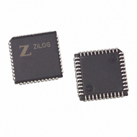
Z86E7216VSC00TR Zilog, Z86E7216VSC00TR Datasheet - Page 36

Z86E7216VSC00TR
Manufacturer Part Number
Z86E7216VSC00TR
Description
IC MCU OTP 16K ZIRC 44PLCC
Manufacturer
Zilog
Series
Z8®r
Datasheet
1.Z86E7216PSC.pdf
(102 pages)
Specifications of Z86E7216VSC00TR
Core Processor
Z8
Core Size
8-Bit
Speed
16MHz
Peripherals
LVD, POR, WDT
Number Of I /o
31
Program Memory Size
16KB (16K x 8)
Program Memory Type
OTP
Ram Size
748 x 8
Voltage - Supply (vcc/vdd)
3 V ~ 5.5 V
Oscillator Type
Internal
Operating Temperature
0°C ~ 70°C
Package / Case
44-LCC (J-Lead)
Lead Free Status / RoHS Status
Contains lead / RoHS non-compliant
Eeprom Size
-
Data Converters
-
Connectivity
-
Available stocks
Company
Part Number
Manufacturer
Quantity
Price
PS008704-0507
Comparator Inputs
Note:
ming the Port 3 Mode Register (bit 1). P31 and P32 are programmable as rising,
falling, or both edge-triggered interrupts (IRQ register bits 6 and 7). Pref1 and P33
are the comparator reference voltage inputs. Access to the Counter Timer edge-
detection circuit is through P31 or P20 (see “CTR1(D)01h Register” on page 48).
Port 3 provides the following control functions: handshake for Ports 0, 1, and 2
(/DAV and RDY); three external interrupt request signals (IRQ2–IRQ0); Data
Memory Select (/DM). See
Table 12. Pin Assignments
Port 3 also provides output for each of the counter/timers and the AND/OR Logic.
Control is performed by programming bits D5–D4 of CTRI, bit 0 of CTR0, and bit 0
of CTR2.
In Analog Mode, Port 3 (P31 and P32) has a comparator front end. The compara-
tor reference is supplied to P33 and Pref1. In this mode, the P33 internal data
latch and its corresponding IRQ1 are diverted to the SMR sources (excluding P31,
P32, and P33) as shown in
Port 3 input register which then generates IRQ1 as shown in Figure 23.
Notes:
HS = Handshake Signals
D = /DAV
R = RDY
Pref1
P31
P32
P33
P34
P35
P36
P37
P20
Pin
Comparators are disabled/powered down by entering STOP
Mode. For P31–P33 to be used as a Stop-Mode recovery
source, these inputs must be placed into digital mode.
OUT
OUT
OUT
OUT
I/O
I/O
IN
IN
IN
IN
T8/16
T16
C/T
T8
IN
IN
Table
Figure
Comp.
RF1
AN1
AN2
RF2
A01
A02
12.
18. In digital mode, P33 is used as D3 of the
IRQ2
IRQ0
IRQ1
Int.
P0 HS
D/R
R/D
P1 HS
D/R
R/D
OTP Microcontroller
P2 HS
D/R
R/D
D/M
Ext
32


