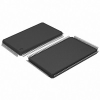
AT91SAM7SE32-AU Atmel, AT91SAM7SE32-AU Datasheet - Page 30

AT91SAM7SE32-AU
Manufacturer Part Number
AT91SAM7SE32-AU
Description
MCU ARM 32K HS FLASH 128-LQFP
Manufacturer
Atmel
Series
AT91SAMr
Specifications of AT91SAM7SE32-AU
Core Processor
ARM7
Core Size
16/32-Bit
Speed
55MHz
Connectivity
EBI/EMI, I²C, SPI, SSC, UART/USART, USB
Peripherals
Brown-out Detect/Reset, POR, PWM, WDT
Number Of I /o
88
Program Memory Size
32KB (32K x 8)
Program Memory Type
FLASH
Ram Size
8K x 8
Voltage - Supply (vcc/vdd)
1.65 V ~ 1.95 V
Data Converters
A/D 8x10b
Oscillator Type
Internal
Operating Temperature
-40°C ~ 85°C
Package / Case
128-LQFP
Controller Family/series
AT91SAM7xxxx
No. Of I/o's
88
Ram Memory Size
8KB
Cpu Speed
48MHz
No. Of Timers
3
Rohs Compliant
Yes
Processor Series
AT91SAMx
Core
ARM7TDMI
Data Bus Width
32 bit
Data Ram Size
8 KB
Interface Type
EBI, SPI, TWI, USART
Maximum Clock Frequency
55 MHz
Number Of Programmable I/os
88
Number Of Timers
3
Maximum Operating Temperature
+ 85 C
Mounting Style
SMD/SMT
3rd Party Development Tools
JTRACE-ARM-2M, KSK-AT91SAM7S-PL, MDK-ARM, RL-ARM, ULINK2
Development Tools By Supplier
AT91SAM-ICE, AT91-ISP, AT91SAM7SE-EK
Minimum Operating Temperature
- 40 C
On-chip Adc
10 bit, 8 Channel
For Use With
AT91SAM7SE-EK - EVAL BOARD FOR AT91SAM7SEAT91SAM-ICE - EMULATOR FOR AT91 ARM7/ARM9
Lead Free Status / RoHS Status
Lead free / RoHS Compliant
Eeprom Size
-
Lead Free Status / Rohs Status
Details
Available stocks
Company
Part Number
Manufacturer
Quantity
Price
Company:
Part Number:
AT91SAM7SE32-AU
Manufacturer:
ATMEL
Quantity:
624
Part Number:
AT91SAM7SE32-AU
Manufacturer:
ATMEL/爱特梅尔
Quantity:
20 000
9.1
9.1.1
9.2
30
Reset Controller
Clock Generator
AT91SAM7SE512/256/32 Preliminary
Brownout Detector and Power On Reset
The AT91SAM7SE512/256/32 embeds one brownout detection circuit and a power-on reset
cell. The power-on reset is supplied with and monitors VDDCORE.
Both signals are provided to the Flash to prevent any code corruption during power-up or power-
down sequences or if brownouts occur on the VDDCORE power supply.
The power-on reset cell has a limited-accuracy threshold at around 1.5V. Its output remains low
during power-up until VDDCORE goes over this voltage level. This signal goes to the reset con-
troller and allows a full re-initialization of the device.
The brownout detector monitors the VDDCORE and VDDFLASH levels during operation by
comparing it to a fixed trigger level. It secures system operations in the most difficult environ-
ments and prevents code corruption in case of brownout on the VDDCORE or VDDFLASH.
When the brownout detector is enabled and VDDCORE decreases to a value below the trigger
level (Vbot18-, defined as Vbot18 - hyst/2), the brownout output is immediately activated.
When VDDCORE increases above the trigger level (Vbot18+, defined as Vbot18 + hyst/2), the
reset is released. The brownout detector only detects a drop if the voltage on VDDCORE stays
below the threshold voltage for longer than about 1µs.
The VDDCORE threshold voltage has a hysteresis of about 50 mV, to ensure spike free brown-
out detection. The typical value of the brownout detector threshold is 1.68V with an accuracy of
± 2% and is factory calibrated.
When the brownout detector is enabled and VDDFLASH decreases to a value below the trigger
level (Vbot33-, defined as Vbot33 - hyst/2), the brownout output is immediately activated.
When VDDFLASH increases above the trigger level (Vbot33+, defined as Vbot33 + hyst/2), the
reset is released. The brownout detector only detects a drop if the voltage on VDDCORE stays
below the threshold voltage for longer than about 1µs.
The VDDFLASH threshold voltage has a hysteresis of about 50 mV, to ensure spike free brown-
out detection. The typical value of the brownout detector threshold is 2.80V with an accuracy of
± 3.5% and is factory calibrated.
The brownout detector is low-power, as it consumes less than 20 µA static current. However, it
can be deactivated to save its static current. In this case, it consumes less than 1µA. The deac-
tivation is configured through the GPNVM bit 0 of the Flash.
The Clock Generator embeds one low-power RC Oscillator, one Main Oscillator and one PLL
with the following characteristics:
• Based on one power-on reset cell and a double brownout detector
• Status of the last reset, either Power-up Reset, Software Reset, User Reset, Watchdog
• Controls the internal resets and the NRST pin output
• Allows to shape a signal on the NRST line, guaranteeing that the length of the pulse meets
• RC Oscillator ranges between 22 KHz and 42 KHz
Reset, Brownout Reset
any requirement.
6222ES–ATARM–15-Dec-09


