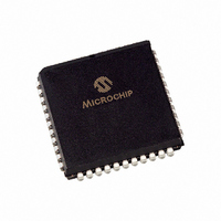
PIC16F877AT-I/L Microchip Technology, PIC16F877AT-I/L Datasheet - Page 120

PIC16F877AT-I/L
Manufacturer Part Number
PIC16F877AT-I/L
Description
IC MCU CMOS 20MHZ 8K FLSH 44PLCC
Manufacturer
Microchip Technology
Series
PIC® 16Fr
Datasheets
1.PIC16F616T-ISL.pdf
(8 pages)
2.PIC16F688T-ISL.pdf
(688 pages)
3.PIC16C770-ISO.pdf
(8 pages)
4.PIC16F873A-ISO.pdf
(234 pages)
5.PIC16F873A-ISO.pdf
(6 pages)
6.PIC16F873A-ISO.pdf
(4 pages)
7.PIC16F873A-ISO.pdf
(6 pages)
8.PIC16F873A-ISO.pdf
(4 pages)
9.PIC16F873A-ISO.pdf
(22 pages)
Specifications of PIC16F877AT-I/L
Core Processor
PIC
Core Size
8-Bit
Speed
20MHz
Connectivity
I²C, SPI, UART/USART
Peripherals
Brown-out Detect/Reset, POR, PWM, WDT
Number Of I /o
33
Program Memory Size
14KB (8K x 14)
Program Memory Type
FLASH
Eeprom Size
256 x 8
Ram Size
368 x 8
Voltage - Supply (vcc/vdd)
4 V ~ 5.5 V
Data Converters
A/D 8x10b
Oscillator Type
External
Operating Temperature
-40°C ~ 85°C
Package / Case
44-PLCC
Processor Series
PIC16F
Core
PIC
Data Bus Width
8 bit
Data Ram Size
368 B
Interface Type
I2C, SPI, USART
Maximum Clock Frequency
20 MHz
Number Of Programmable I/os
33
Number Of Timers
1 x 16 bit
Operating Supply Voltage
2 V to 5.5 V
Maximum Operating Temperature
+ 85 C
Mounting Style
SMD/SMT
3rd Party Development Tools
52715-96, 52716-328, 52717-734
Development Tools By Supplier
PG164130, DV164035, DV244005, DV164005, PG164120, ICE2000, DM163022, DV164120
Minimum Operating Temperature
- 40 C
On-chip Adc
8
For Use With
DVA16XL441 - ADAPTER DEVICE ICE 44PLCC309-1040 - ADAPTER 44-PLCC ZIF TO 40-DIP309-1039 - ADAPTER 44-PLCC TO 40-DIP
Lead Free Status / RoHS Status
Lead free / RoHS Compliant
Available stocks
Company
Part Number
Manufacturer
Quantity
Price
Company:
Part Number:
PIC16F877AT-I/L
Manufacturer:
Microchip Technology
Quantity:
10 000
- PIC16F616T-ISL PDF datasheet
- PIC16F688T-ISL PDF datasheet #2
- PIC16C770-ISO PDF datasheet #3
- PIC16F873A-ISO PDF datasheet #4
- PIC16F873A-ISO PDF datasheet #5
- PIC16F873A-ISO PDF datasheet #6
- PIC16F873A-ISO PDF datasheet #7
- PIC16F873A-ISO PDF datasheet #8
- PIC16F873A-ISO PDF datasheet #9
- Current page: 120 of 688
- Download datasheet (3Mb)
PICmicro MID-RANGE MCU FAMILY
7.11
DS31007A-page 7-8
Design Tips
Question 1:
Answer 1:
There are a few possibilities, but the most likely is that you did not exactly follow the write
sequence as shown in
are disabled during this sequence.
Question 2:
Answer 2:
The data will only change when a Data EEPROM write occurs. Inadvertent writes may occur
when the device is in a brown-out condition (out of operating specification) and the device is not
being forced to the reset state. During a brown-out, either the internal brown-out circuitry should
be enabled (when available) or external circuitry should be used to reset the PICmicro MCU to
ensure that no data EEPROM writes occur when the device is out of the valid operating range.
Why do the data EEPROM locations not contain the data that I wrote?
Why is the data in the data EEPROM is getting corrupted?
Example
7-2. If you are using this code segment ensure that all interrupts
1997 Microchip Technology Inc.
Related parts for PIC16F877AT-I/L
Image
Part Number
Description
Manufacturer
Datasheet
Request
R

Part Number:
Description:
Manufacturer:
Microchip Technology Inc.
Datasheet:

Part Number:
Description:
IC MCU FLASH 8KX14 EE 40DIP
Manufacturer:
Microchip Technology
Datasheet:

Part Number:
Description:
IC MCU FLASH 8KX14 EE 40DIP
Manufacturer:
Microchip Technology
Datasheet:

Part Number:
Description:
IC MCU FLASH 8KX14 EE 40DIP
Manufacturer:
Microchip Technology
Datasheet:

Part Number:
Description:
IC MCU FLASH 8KX14 EE 40DIP
Manufacturer:
Microchip Technology
Datasheet:

Part Number:
Description:
IC MCU FLASH 8KX14 EE 44PLCC
Manufacturer:
Microchip Technology
Datasheet:

Part Number:
Description:
IC MCU FLASH 8KX14 EE 44TQFP
Manufacturer:
Microchip Technology
Datasheet:

Part Number:
Description:
IC MCU FLASH 8KX14 EE 44TQFP
Manufacturer:
Microchip Technology
Datasheet:

Part Number:
Description:
IC MCU FLASH 8KX14 EE 44TQFP
Manufacturer:
Microchip Technology
Datasheet:

Part Number:
Description:
IC MCU FLASH 8KX14 EE 44PLCC
Manufacturer:
Microchip Technology
Datasheet:

Part Number:
Description:
IC MCU FLASH 8KX14 EE 44TQFP
Manufacturer:
Microchip Technology
Datasheet:

Part Number:
Description:
IC MCU FLASH 8KX14 EE 44-MQFP
Manufacturer:
Microchip Technology
Datasheet:

Part Number:
Description:
IC MCU FLASH 8KX14 EE 44-MQFP
Manufacturer:
Microchip Technology
Datasheet:

Part Number:
Description:
IC MCU FLASH 8KX14 EE 44TQFP
Manufacturer:
Microchip Technology
Datasheet:


