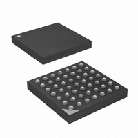
ATXMEGA16D4-CU Atmel, ATXMEGA16D4-CU Datasheet - Page 20

ATXMEGA16D4-CU
Manufacturer Part Number
ATXMEGA16D4-CU
Description
MCU AVR 16KB FLASH 49VFBGA
Manufacturer
Atmel
Series
AVR® XMEGAr
Datasheet
1.ATXMEGA16D4-AU.pdf
(105 pages)
Specifications of ATXMEGA16D4-CU
Core Processor
AVR
Core Size
8/16-Bit
Speed
32MHz
Connectivity
I²C, IrDA, SPI, UART/USART
Peripherals
Brown-out Detect/Reset, POR, PWM, WDT
Number Of I /o
34
Program Memory Size
16KB (8K x 16)
Program Memory Type
FLASH
Eeprom Size
1K x 8
Ram Size
2K x 8
Voltage - Supply (vcc/vdd)
1.6 V ~ 3.6 V
Data Converters
A/D 12x12b
Oscillator Type
Internal
Operating Temperature
-40°C ~ 85°C
Package / Case
49-VFBGA
Processor Series
ATXMEGA16x
Core
AVR8
Data Bus Width
8 bit
Data Ram Size
8 KB
Interface Type
2-Wire, SPI
Maximum Clock Frequency
32 MHz
Number Of Programmable I/os
34
Number Of Timers
4
Operating Supply Voltage
1.6 V to 3.6 V
Maximum Operating Temperature
+ 85 C
Mounting Style
SMD/SMT
3rd Party Development Tools
EWAVR, EWAVR-BL
Development Tools By Supplier
ATAVRDRAGON, ATSTK500, ATSTK600, ATAVRISP2, ATAVRONEKIT
Minimum Operating Temperature
- 40 C
On-chip Adc
12 bit, 12 Channel
On-chip Dac
12 bit, 12 Channel
Lead Free Status / RoHS Status
Lead free / RoHS Compliant
Available stocks
Company
Part Number
Manufacturer
Quantity
Price
10. Power Management and Sleep Modes
10.1
10.2
10.3
10.3.1
10.3.2
10.3.3
8135J–AVR–12/10
Features
Overview
Sleep Modes
Idle Mode
Power-down Mode
Power-save Mode
•
•
XMEGA provides various sleep modes and software controlled clock gating in order to tailor
power consumption to the application's requirement. Sleep modes enables the microcontroller to
shut down unused modules to save power. When the device enters sleep mode, program exe-
cution is stopped and interrupts or reset is used to wake the device again. The individual clock to
unused peripherals can be stopped during normal operation or in sleep, enabling a much more
fine tuned power management than sleep modes alone
Sleep modes are used to shut down modules and clock domains in the microcontroller in order
to save power. XMEGA has five different sleep modes. A dedicated Sleep instruction (SLEEP) is
available to enter sleep. Before executing SLEEP, the selected sleep mode to enter must be
configured. The available interrupt wake-up sources is dependent on the selected sleep mode.
When an enabled interrupt occurs the device will wake up and execute the interrupt service rou-
tine before continuing normal program execution from the first instruction after the SLEEP
instruction. If other higher priority interrupts are pending when the wake-up occurs, their interrupt
service routines will be executed according to their priority before the interrupt service routine for
the wake-up interrupt is executed. After wake-up the CPU is halted for four cycles before execu-
tion starts.
In Idle mode the CPU and Non-Volatile Memory are stopped, but all peripherals including the
Interrupt Controller and Event System are kept running. Interrupt requests from all enabled inter-
rupts will wake the device.
In Power-down mode all system clock sources, and the asynchronous Real Time Counter (RTC)
clock source, are stopped. This allows operation of asynchronous modules only. The only inter-
rupts that can wake up the MCU are the Two Wire Interface address match interrupts, and
asynchronous port interrupts.
Power-save mode is identical to Power-down, with one exception:
If the Real Time Counter (RTC) is enabled, it will keep running during sleep and the device can
also wake up from either RTC Overflow or Compare Match interrupt.
5 sleep modes
Power Reduction registers to disable clocks to unused peripherals
– Idle
– Power-down
– Power-save
– Standby
– Extended standby
XMEGA D4
20


