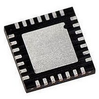
PIC18LF27J13-I/ML Microchip Technology, PIC18LF27J13-I/ML Datasheet - Page 11

PIC18LF27J13-I/ML
Manufacturer Part Number
PIC18LF27J13-I/ML
Description
IC PIC MCU 128KB FLASH 28QFN
Manufacturer
Microchip Technology
Series
PIC® XLP™ 18Fr
Datasheets
1.PIC18LF24J10-ISS.pdf
(32 pages)
2.PIC18F26J13-ISS.pdf
(496 pages)
3.PIC18F26J13-ISS.pdf
(558 pages)
4.PIC18F26J13-ISS.pdf
(12 pages)
Specifications of PIC18LF27J13-I/ML
Core Size
8-Bit
Program Memory Size
128KB (64K x 16)
Core Processor
PIC
Speed
48MHz
Connectivity
I²C, LIN, SPI, UART/USART
Peripherals
Brown-out Detect/Reset, POR, PWM, WDT
Number Of I /o
22
Program Memory Type
FLASH
Ram Size
3.8K x 8
Voltage - Supply (vcc/vdd)
2 V ~ 2.75 V
Data Converters
A/D 10x10b/12b
Oscillator Type
Internal
Operating Temperature
-40°C ~ 85°C
Package / Case
*
Controller Family/series
PIC18
Cpu Speed
48MHz
Digital Ic Case Style
QFN
Supply Voltage Range
1.8V To 3.6V
Embedded Interface Type
I2C, SPI, USART
Rohs Compliant
Yes
Lead Free Status / RoHS Status
Lead free / RoHS Compliant
Eeprom Size
-
Lead Free Status / RoHS Status
Lead free / RoHS Compliant, Lead free / RoHS Compliant
- PIC18LF24J10-ISS PDF datasheet
- PIC18F26J13-ISS PDF datasheet #2
- PIC18F26J13-ISS PDF datasheet #3
- PIC18F26J13-ISS PDF datasheet #4
- Current page: 11 of 496
- Download datasheet (5Mb)
Table of Contents
1.0
2.0
3.0
4.0
5.0
6.0
7.0
8.0
9.0
10.0 I/O Ports .................................................................................................................................................................................. 133
11.0 Timer0 Module ........................................................................................................................................................................ 157
12.0 Timer1/3/5 Module with Gate Control...................................................................................................................................... 161
13.0 Timer2/4/6 Module .................................................................................................................................................................. 173
14.0 Capture/Compare/PWM Modules ........................................................................................................................................... 177
15.0 Master Synchronous Serial Port (MSSP1 and MSSP2) Module ............................................................................................. 207
16.0 Enhanced Universal Synchronous Asynchronous Receiver Transmitter (EUSART) .............................................................. 263
17.0 Analog-to-Digital Converter (ADC) Module ............................................................................................................................. 291
18.0 Comparator Module................................................................................................................................................................. 305
19.0 Charge Time Measurement Unit (CTMU)................................................................................................................................ 317
20.0 SR L
21.0 Fixed Voltage Reference (FVR) .............................................................................................................................................. 337
22.0 Digital-to-Analog Converter (DAC) Module ............................................................................................................................. 339
23.0 High/Low-Voltage Detect (HLVD) ............................................................................................................................................ 343
24.0 Special Features of the CPU ................................................................................................................................................... 349
25.0 Instruction Set Summary ......................................................................................................................................................... 367
26.0 Development Support.............................................................................................................................................................. 417
27.0 Electrical Characteristics ......................................................................................................................................................... 421
28.0 DC and AC Characteristics Graphs and Tables ...................................................................................................................... 461
29.0 Packaging Information............................................................................................................................................................. 463
Appendix A: Revision History............................................................................................................................................................ 481
Appendix B: Device Differences........................................................................................................................................................ 482
Index ................................................................................................................................................................................................. 483
The Microchip Web Site .................................................................................................................................................................... 493
Customer Change Notification Service ............................................................................................................................................. 493
Customer Support ............................................................................................................................................................................. 493
Reader Response ............................................................................................................................................................................. 494
Product Identification System ........................................................................................................................................................... 495
2010 Microchip Technology Inc.
Device Overview ....................................................................................................................................................................... 13
Oscillator Module (With Fail-Safe Clock Monitor)) .................................................................................................................... 27
Power-Managed Modes ............................................................................................................................................................ 47
Reset ......................................................................................................................................................................................... 59
Memory Organization ................................................................................................................................................................ 69
Flash Program Memory............................................................................................................................................................. 95
Data EEPROM Memory .......................................................................................................................................................... 105
8 X 8 Hardware Multiplier ......................................................................................................................................................... 111
Interrupts .................................................................................................................................................................................. 113
ATCH
................................................................................................................................................................................. 333
Preliminary
PIC18(L)F2X/4XK22
DS41412D-page 11
Related parts for PIC18LF27J13-I/ML
Image
Part Number
Description
Manufacturer
Datasheet
Request
R

Part Number:
Description:
Manufacturer:
Microchip Technology Inc.
Datasheet:

Part Number:
Description:
Manufacturer:
Microchip Technology Inc.
Datasheet:

Part Number:
Description:
Manufacturer:
Microchip Technology Inc.
Datasheet:

Part Number:
Description:
Manufacturer:
Microchip Technology Inc.
Datasheet:

Part Number:
Description:
Manufacturer:
Microchip Technology Inc.
Datasheet:

Part Number:
Description:
Manufacturer:
Microchip Technology Inc.
Datasheet:

Part Number:
Description:
Manufacturer:
Microchip Technology Inc.
Datasheet:

Part Number:
Description:
Manufacturer:
Microchip Technology Inc.
Datasheet:


