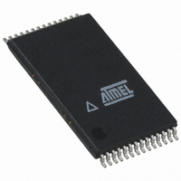
ATMEGA16HVA-4TU Atmel, ATMEGA16HVA-4TU Datasheet - Page 124

ATMEGA16HVA-4TU
Manufacturer Part Number
ATMEGA16HVA-4TU
Description
MCU AVR 16K FLASH 4MHZ 28-TSOP
Manufacturer
Atmel
Series
AVR® ATmegar
Datasheet
1.ATMEGA16HVA-4CKU.pdf
(196 pages)
Specifications of ATMEGA16HVA-4TU
Core Processor
AVR
Core Size
8-Bit
Speed
4MHz
Connectivity
SPI
Peripherals
Brown-out Detect/Reset, POR, PWM, WDT
Number Of I /o
7
Program Memory Size
16KB (8K x 16)
Program Memory Type
FLASH
Eeprom Size
256 x 8
Ram Size
512 x 8
Voltage - Supply (vcc/vdd)
1.8 V ~ 9 V
Data Converters
A/D 5x12b
Oscillator Type
External
Operating Temperature
-20°C ~ 85°C
Package / Case
28-TSOP
For Use With
ATSTK600 - DEV KIT FOR AVR/AVR32ATSTK500 - PROGRAMMER AVR STARTER KIT
Lead Free Status / RoHS Status
Lead free / RoHS Compliant
Available stocks
Company
Part Number
Manufacturer
Quantity
Price
Company:
Part Number:
ATMEGA16HVA-4TU
Manufacturer:
Atmel
Quantity:
20
- Current page: 124 of 196
- Download datasheet (3Mb)
23. Battery Protection
23.1
23.2
Table 23-1.
124
Battery Protection Type
Short-circuit Protection
Discharge Over-current
Protection
Charge Over-current
Protection
Discharge High-current
Protection
Charge High-current
Protection
Features
Overview
ATmega8HVA/16HVA
Effect of Battery Protection Types
•
•
•
•
•
•
•
The Current Battery Protection circuitry (CBP) monitors the charge and discharge current and
disables C-FET and D-FET if a Short-circuit, Over-current or High-current condition is detected.
There are five different programmable detection levels: Short-circuit Detection Level, Discharge
Over-current Detection Level, Charge Over-current Detection Level, Discharge High-current
Detection Level, Charge High-current Detection Level. There are three different programmable
delays for activating Current Battery Protection: Short-circuit Reaction Time, Over-current Reac-
tion Time and High-current Reaction Time. After Current Battery Protection has been activated,
the application software must re-enable the FETs. The Battery Protection hardware provides a
hold-off time of 1 second before software can re-enable the discharge FET. This provides safety
in case the application software should unintentionally re-enable the discharge FET too early.
The activation of a protection also issues an interrupt to the CPU. The battery protection inter-
rupts can be individually enabled and disabled by the CPU.
The effect of the various battery protection types is given in
In order to reduce power consumption, Short-circuit, Discharge High-current and Discharge
Over-current Protection are automatically deactivated when the D-FET is disabled. The Charge
Over-current and Charge High-current Protection are disabled when the C-FET is disabled. Note
however that Charge Over-current Protection and Charge High-current Protection are never
automatically disabled when the chip is operated in DUVR mode.
Short-circuit Protection
Discharge Over-current Protection
Charge Over-current Protection
Discharge High-current Protection
Charge High-current Protection
Programmable and Lockable Detection Levels and Reaction Times
Autonomous Operation Independent of CPU
Interrupt Requests
Entry
Entry
Entry
Entry
Entry
Disabled
Disabled
Disabled
Disabled
Disabled
C-FET
Disabled
Disabled
Disabled
Disabled
Disabled
D-FET
Table
23-1.
Operational
Operational
Operational
Operational
Operational
MCU
8024A–AVR–04/08
Related parts for ATMEGA16HVA-4TU
Image
Part Number
Description
Manufacturer
Datasheet
Request
R

Part Number:
Description:
Manufacturer:
Atmel Corporation
Datasheet:

Part Number:
Description:
IC AVR MCU 16K 16MHZ 5V 44TQFP
Manufacturer:
Atmel
Datasheet:

Part Number:
Description:
IC AVR MCU 16K 16MHZ 5V 44-QFN
Manufacturer:
Atmel
Datasheet:

Part Number:
Description:
IC AVR MCU 16K 16MHZ 5V 40DIP
Manufacturer:
Atmel
Datasheet:

Part Number:
Description:
MCU AVR 16K FLASH 16MHZ 44-QFN
Manufacturer:
Atmel
Datasheet:

Part Number:
Description:
IC AVR MCU 16K 16MHZ COM 40-DIP
Manufacturer:
Atmel
Datasheet:

Part Number:
Description:
IC AVR MCU 16K 16MHZ COM 44-QFN
Manufacturer:
Atmel
Datasheet:

Part Number:
Description:
IC AVR MCU 16K 16MHZ IND 40-DIP
Manufacturer:
Atmel
Datasheet:

Part Number:
Description:
IC AVR MCU 16K 16MHZ IND 44-QFN
Manufacturer:
Atmel
Datasheet:

Part Number:
Description:
IC AVR MCU 16K 16MHZ IND 44-TQFP
Manufacturer:
Atmel
Datasheet:

Part Number:
Description:
IC MCU 8BIT 16KB FLASH 44TQFP
Manufacturer:
Atmel
Datasheet:

Part Number:
Description:
MCU AVR 16K FLASH 16MHZ 44-TQFP
Manufacturer:
Atmel
Datasheet:

Part Number:
Description:
IC AVR MCU 16K 16MHZ COM 44-TQFP
Manufacturer:
Atmel
Datasheet:


