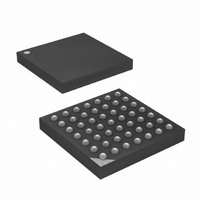
ATXMEGA16A4-CUR Atmel, ATXMEGA16A4-CUR Datasheet - Page 23

ATXMEGA16A4-CUR
Manufacturer Part Number
ATXMEGA16A4-CUR
Description
MCU AVR 16+4KB FLASH 49VFBGA
Manufacturer
Atmel
Series
AVR® XMEGAr
Specifications of ATXMEGA16A4-CUR
Core Processor
AVR
Core Size
8/16-Bit
Speed
32MHz
Connectivity
I²C, IrDA, SPI, UART/USART
Peripherals
Brown-out Detect/Reset, DMA, POR, PWM, WDT
Number Of I /o
34
Program Memory Size
16KB (8K x 16)
Program Memory Type
FLASH
Eeprom Size
1K x 8
Ram Size
2K x 8
Voltage - Supply (vcc/vdd)
1.6 V ~ 3.6 V
Data Converters
A/D 12x12b, D/A 2x12b
Oscillator Type
Internal
Operating Temperature
-40°C ~ 85°C
Package / Case
49-VFBGA
For Use With
ATAVRONEKIT - KIT AVR/AVR32 DEBUGGER/PROGRMMRATSTK600 - DEV KIT FOR AVR/AVR32770-1007 - ISP 4PORT ATMEL AVR MCU SPI/JTAG770-1004 - ISP 4PORT FOR ATMEL AVR MCU SPI
Lead Free Status / RoHS Status
Lead free / RoHS Compliant
Available stocks
Company
Part Number
Manufacturer
Quantity
Price
12. System Control and Reset
12.1
12.2
12.3
12.3.1
12.3.2
12.3.3
12.3.4
8069Q–AVR–12/10
Features
Resetting the AVR
Reset Sources
Power-On Reset
External Reset
Watchdog Reset
Brown-Out Reset
•
•
•
During reset, all I/O registers are set to their initial values. The SRAM content is not reset. Appli-
cation execution starts from the Reset Vector. The instruction placed at the Reset Vector should
be an Absolute Jump (JMP) instruction to the reset handling routine. By default the Reset Vector
address is the lowest Flash program memory address, ‘0’, but it is possible to move the Reset
Vector to the first address in the Boot Section.
The I/O ports of the AVR are immediately tri-stated when a reset source goes active.
The reset functionality is asynchronous, so no running clock is required to reset the device.
After the device is reset, the reset source can be determined by the application by reading the
Reset Status Register.
The MCU is reset when the supply voltage VCC is below the Power-on Reset threshold voltage.
The MCU is reset when a low level is present on the RESET pin.
The MCU is reset when the Watchdog Timer period expires and the Watchdog Reset is enabled.
The Watchdog Timer runs from a dedicated oscillator independent of the System Clock. For
more details see
The MCU is reset when the supply voltage VCC is below the Brown-Out Reset threshold voltage
and the Brown-out Detector is enabled. The Brown-out threshold voltage is programmable.
Multiple reset sources for safe operation and device reset
Asynchronous reset
Reset status register
– Power-On Reset
– External Reset
– Watchdog Reset
– Brown-Out Reset
– PDI reset
– Software reset
– No running clock in the device is required for reset
The Watchdog Timer runs from separate, dedicated oscillator
Accurate, programmable Brown-Out levels
”WDT - Watchdog Timer” on page
24.
XMEGA A4
23


