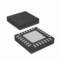
ATTINY48-MMH Atmel, ATTINY48-MMH Datasheet - Page 2

ATTINY48-MMH
Manufacturer Part Number
ATTINY48-MMH
Description
MCU AVR 4KB FLASH 12MHZ 28-VQFN
Manufacturer
Atmel
Series
AVR® ATtinyr
Specifications of ATTINY48-MMH
Core Processor
AVR
Core Size
8-Bit
Speed
12MHz
Connectivity
I²C, SPI
Peripherals
Brown-out Detect/Reset, POR, WDT
Number Of I /o
24
Program Memory Size
4KB (2K x 16)
Program Memory Type
FLASH
Eeprom Size
64 x 8
Ram Size
256 x 8
Voltage - Supply (vcc/vdd)
1.8 V ~ 5.5 V
Data Converters
A/D 6x10b
Oscillator Type
Internal
Operating Temperature
-40°C ~ 85°C
Package / Case
28-VQFN Exposed Pad, 28-HVQFN, 28-SQFN, 28-DHVQFN
For Use With
ATAVRDRAGON - KIT DRAGON 32KB FLASH MEM AVR
Lead Free Status / RoHS Status
Lead free / RoHS Compliant
2 General Porting Considerations
3 Pin Configurations
2
AVR515
To make the porting process as easy as possible, one should always refer to
registers and bit positions using their defined names and avoid using absolute
addresses and values. In most cases, register and bit names are unchanged from
device to device. When porting a design it is more convenient to include the correct
definition file for the new device, rather than manually changing all addresses and bit
values. It is also considered good programming practice to use named references
instead of absolute values. Some examples are shown below.
To avoid conflicts with added features and register functionality, never access
registers that are marked as reserved. Reserved bits should always be written zero, if
accessed. This ensures forward compatibility, and added features will stay in their
default states when unused.
Pin output drivers have been optimized for size in ATtiny48/88. Drive strengths are
summarised in the table below.
Table 3-1. Pin drive strengths.
ATtiny48/88
ATmega48P/88P/168P/328P by default, although some pin functions have been
removed and other functions have been added. These changes should not affect pin
compatibility by default but have been listed in the table below for clarity.
Table 3-2. Pin configurations.
Supply voltage
5 V
3 V
TQFP
PORTB |=
DDRB
// Configure USI
USICR
1
2
3
6
&= ~(1<<PORTB3);
=
MLF
1
2
3
6
(1<<PORTB3);
(1<<USISIE)|(0<<USIOIE)|(1<<USIWM1)|(0<<USIWM0)|
(1<<USICS1)|(0<<USICS0)|(0<<USICLK)|(0<<USITC);
is
Pin
PDIP
ATmega168
ATmega48
ATmega88
5
6
-
-
20 mA
10 mA
pin-compatible
GND (PA2)
VCC (PA3)
Name
PD3
PD4
ATmega168P
ATmega328P
ATmega48P
ATmega88P
// Set pin 3 on port B high
// Set pin 3 on port B as input
20 mA
10 mA
Change
Removed: OC2B
Removed: XCK
Changed: GND to PCINT26 / PA2
Changed: VCC to PCINT27 / PA3
with
Normal I/O
ATmega48/88/168
10 mA
5 mA
ATtiny48
ATtiny88
8089A-AVR-09/07
High Sink
20 mA
10 mA
and


