DS5001FP-16N+ Maxim Integrated Products, DS5001FP-16N+ Datasheet
DS5001FP-16N+
Specifications of DS5001FP-16N+


Related parts for DS5001FP-16N+


DS5001FP-16N+ Summary of contents
Page 1
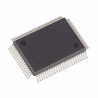
... BA13 8 P0.1/AD1 9 DS5001FP R/W 10 P0.0/AD0 11 VCC0 12 VCC 13 MSEL 14 P1.0 15 BA14 16 P1.1 17 BA12 18 P1.2 19 BA7 20 P1.3 21 PE3 22 PE4 23 BA6 MQFP MQFP DS5001FP 64 P2.6/A14 63 CE3 62 CE4 61 BD3 60 P2.5/A13 59 BD2 58 P2.4/A12 57 BD1 56 P2.3/A11 55 BD0 54 VLI 53 BA15 52 GND 51 P2.2/A10 50 P2.1/A9 49 P2.0/A8 48 XTAL1 47 XTAL2 46 P3.7/RD 45 P3.6/ ...
Page 2
... ORDERING INFORMATION PART TEMP RANGE DS5001FP-16 0°C to +70°C DS5001FP-16+ 0°C to +70°C DS5001FP-16N -40°C to +85°C DS5001FP-16N+ -40°C to +85°C DS5001FP-12-44 0°C to +70°C DS5001FP-12-44+ 0°C to +70°C + Denotes a Pb-free/RoHS-compliant device. DESCRIPTION The DS5001FP 128k soft microprocessor chip is an 8051-compatible microprocessor based on NV RAM technology and designed for systems that need large quantities of nonvolatile memory ...
Page 3
... Figure 1. BLOCK DIAGRAM DS5001FP ...
Page 4
... At this PSEN time, is pulled down externally. This should only be done once the DS5001FP PSEN is already in a reset state. The device that pulls down should be open drain since it must not interfere with under normal operation. ...
Page 5
... CE3 . LI is lithium-backed and remains at a logic high to battery-backed functions only. PE1 is lithium-backed and remains at a logic PE2 to battery-backed functions only. PE2 is not lithium-backed and can be connected PE3 is not lithium-backed and can be connected PE4 DS5001FP through . LI < < < ...
Page 6
... SRAM, a lithium cell, and a real-time clock. This is packaged in a 72-pin SIMM module. MEMORY ORGANIZATION Figure 2 illustrates the memory map accessed by the DS5001FP. The entire 64k of program and 64k of data are potentially available to the byte-wide bus. This preserves the I/O ports for application use. The user controls the portion of memory that is actually mapped to the byte-wide bus by selecting the program range and data range ...
Page 7
... Figure 2. MEMORY MAP IN NONPARTITIONABLE MODE ( DS5001FP ...
Page 8
... Figure 3. MEMORY MAP IN PARTITIONABLE MODE ( NOTE: PARTITIONABLE MODE IS NOT SUPPORTED WHEN MSEL PIN = 0 (128kB MODE DS5001FP ...
Page 9
... Figure 4. MEMORY MAP WITH PES = DS5001FP ...
Page 10
... RAM chip Figure 6 shows a similar system with using two 32kB SRAMs. The byte-wide address bus connects to the SRAM address lines. The bidirectional byte-wide data bus connects the data I/O lines of the SRAM. Figure 5. CONNECTION TO 128k x 8 SRAM DS5001FP ...
Page 11
... Low power SRAMs should be used for this reason. When using the DS5001FP, the user must select the appropriate battery to match the RAM data retention current and the desired backup lifetime. Note that the lithium cell is only loaded when V more information on this topic ...
Page 12
... Transition Current 2.0V (Ports (-40°C to +85°C) SYMBOL MIN V -0 2.0 IH1 V 3.5 IH2 V OL1 ) , V OL2 V 2.4 OH1 , PSEN V 2.4 OH2 , and TYP MAX UNITS + 0.15 0.45 V 0.15 0.45 V 4.8 V 4.8 V -50 µA -500 µA -600 µA DS5001FP + 0.5V 0V. In NOTES ...
Page 13
... 4.25 4.37 PFW V 4.1 4.37 PFW V 4.00 4.12 CCMIN V 3.85 4.09 CCMIN CCMIN V 2 IDLE I IDLE I STOP CCO1 -0. CCO2 -0. CCO2 -0.9 I CCO1 4.0 3.85 4 DS5001FP MAX UNITS NOTES +10 µA 150 kW 180 µ 500 nA 7 4. 4.65 ...
Page 14
... CLK CLK 3t - 150 CLK CLK CLK CLK 5t - 150 CLK CLK 100 CLK 6t - 100 CLK 5t - 165 CLK 5t - 105 CLK CLK 8t - 150 CLK CLK 9t - 165 CLK 9t - 105 CLK CLK CLK 4t - 130 CLK CLK 7t - 150 CLK CLK CLK CLK CLK DS5001FP UNITS MHz ...
Page 15
... EXPANDED PROGRAM-MEMORY READ CYCLE EXPANDED DATA-MEMORY READ CYCLE DS5001FP ...
Page 16
... EXPANDED DATA-MEMORY WRITE CYCLE DS5001FP ...
Page 17
... AC CHARACTERISTICS: EXTERNAL CLOCK DRIVE ( ±10 0°C to +70°C PARAMETER 28 External Clock-High Time 29 External Clock-Low Time 30 External Clock-Rise Time 31 External Clock-Fall Time EXTERNAL CLOCK TIMING SYMBOL at 12MHz t CLKHPW at 16MHz at 12MHz t CLKLPW at 16MHz at 12MHz t CLKR at 16MHz at 12MHz t CLKF at 16MHz DS5001FP MIN MAX UNITS ...
Page 18
... AC CHARACTERISTICS: POWER CYCLE TIME ( ±10 0°C to +70°C PARAMETER 32 Slew Rate from V CCMIN 33 Crystal Startup Time 34 Power-On Reset Delay POWER CYCLE TIMING SYMBOL CSU t POR DS5001FP MIN MAX UNITS 130 µs (Note 9) 21,504 t CLK ...
Page 19
... Output-Data Setup to Rising-Clock Edge 37 Output-Data Hold After Rising-Clock Edge 38 Clock-Rising Edge to Input-Data Valid 39 Input-Data Hold After Rising-Clock Edge SERIAL PORT TIMING—MODE 0 SYMBOL MIN t 12t SPCLK CLK t 10t - 133 DOCH CLK 117 CHDO CLK t CHDV t 0 CHDIV DS5001FP MAX UNITS µ 10t - 133 ns CLK ns ...
Page 20
... Low During MOVX 1-4, 1- 1-4, CE Active W 1-4, CE High W Low Time MIN MAX t 30 CE1LPA CEPW CLK CE1HPA CLK OVCE1H CLK t 0 CE1HOV CEHDA CLK CELDA CLK DACEH CLK t 0 CEHDV AVRWL CLK t 20 RWLDV CEHDV CLK t 0 RWHDV RWLPW CLK DS5001FP UNITS ...
Page 21
... RPC AC CHARACTERISTICS: DBB WRITE ( ±10 0°C to +70°C PARAMETER Setup 61A , Hold After CS WR 61B A , Hold After Pulse Width WR 63 Data Setup Data Hold After WR SYMBOL MIN 160 RDZ SYMBOL MIN 160 WW t 130 DS5001FP MAX UNITS 130 ns 130 MAX UNITS ...
Page 22
... DACK DACK 67 to Data Valid DACK DRQ Cleared CHARACTERISTICS ±10 0°C to +70°C PARAMETER 69 Low to Active PROG 70 High to Inactive PROG SYMBOL t ACC t CAC t ACD t CRQ PROG SYMBOL t PRA t PRI DS5001FP MIN MAX UNITS 130 ns 110 ns MIN MAX UNITS 48 CLKS 48 CLKS ...
Page 23
... RPC TIMING MODE DS5001FP ...
Page 24
... The user should check with the crystal vendor for a worst-case specification on this time. 10) This parameter applies to industrial temperature operation. 11) pin operation is specified with input when and < and a maximum load of 10µ ³ 3.0V. BAT MSEL = RST = MSEL = XTAL2 not CC = +25° normal operation. CCO is disconnected. CCO . CCO DS5001FP , CLKR , CLKR ...
Page 25
... For the latest package outline information www.maxim-ic.com/DallasPackInfo.) 80-PIN MQFP MM DIM MIN MAX A - 3. 2.55 2.87 B 0.30 0.50 C 0.13 0.23 D 23.70 24.10 D1 19.90 20.10 E 17.70 18.10 E1 13.90 14.10 e 0.80 BSC L 0.65 0.95 56-G4005-001 DS5001FP ...
Page 26
... MQFP DS5001FP ...
Page 27
... The following represent the key differences between the 051099 and 052499 version of the DS5001FP data sheet. Please review this summary carefully. 1) Minor markups and ready for approval. The following represent the key differences between the 052499 and 052302 version of the DS5001FP data sheet. Please review this summary carefully. 1) Added information relating to 44-pin package. ...