MCF51JM128EVLK Freescale Semiconductor, MCF51JM128EVLK Datasheet - Page 26
MCF51JM128EVLK
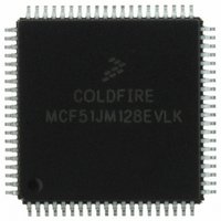
Manufacturer Part Number
MCF51JM128EVLK
Description
IC MCU 128/16K FLASH/SRAM 80LQFP
Manufacturer
Freescale Semiconductor
Series
MCF51JMr
Specifications of MCF51JM128EVLK
Core Processor
Coldfire V1
Core Size
32-Bit
Speed
50MHz
Connectivity
CAN, I²C, SCI, SPI, USB OTG
Peripherals
LVD, PWM, WDT
Number Of I /o
66
Program Memory Size
128KB (128K x 8)
Program Memory Type
FLASH
Ram Size
16K x 8
Voltage - Supply (vcc/vdd)
2.7 V ~ 5.5 V
Data Converters
A/D 12x12b
Oscillator Type
External
Operating Temperature
-40°C ~ 105°C
Package / Case
80-LQFP
Processor Series
MCF51JM
Core
ColdFire V1
Data Bus Width
32 bit
Data Ram Size
16 KB
Interface Type
SPI, SCI
Maximum Clock Frequency
50.33 MHz
Number Of Programmable I/os
66
Number Of Timers
9
Maximum Operating Temperature
+ 105 C
Mounting Style
SMD/SMT
3rd Party Development Tools
JLINK-CF-BDM26, EWCF
Development Tools By Supplier
DEMOJM, DEMOFLEXISJMSD, EVB51JM128
Minimum Operating Temperature
- 40 C
On-chip Adc
12 bit, 12 Channel
For Use With
EVB51JM128 - BOARD EVAL FOR MCF51JM128 MCUDEMOJMSKT - BOARD DEMO S08JM CARD W/SOCKET
Lead Free Status / RoHS Status
Lead free / RoHS Compliant
Eeprom Size
-
Lead Free Status / Rohs Status
Lead free / RoHS Compliant
Available stocks
Company
Part Number
Manufacturer
Quantity
Price
Company:

Part Number:
MCF51JM128EVLK
Manufacturer:
Freescale Semiconductor
Quantity:
10 000


1
2
3
4
5
Num C
Preliminary Electrical Characteristics
2.9
26
Data in Typical column was characterized at 5.0 V, 25°C or is typical recommended value.
When MCG is configured for FEE or FBE mode, input clock source must be divisible using RDIV to within the range of 31.25 kHz
to 39.0625 kHz.
When MCG is configured for PEE or PBE mode, input clock source must be divisible using RDIV to within the range of 1 MHz
to 2 MHz.
This parameter is characterized and not tested on each device. Proper PC board-layout procedures must be followed to achieve
specifications.
4 MHz crystal
1
2
3
4
5
6
—
T
T
Table 15. Oscillator Electrical Specifications (Temperature Range = –40 to 105°C Ambient)
Oscillator crystal or resonator (EREFS = 1, ERCLKEN = 1)
Load capacitors
Feedback resistor
Series resistor
Crystal start-up time
Square wave input clock frequency (EREFS = 0, ERCLKEN = 1)
• Low range (RANGE = 0)
• High range (RANGE = 1) FEE or FBE mode
• High range (RANGE = 1) PEE or PBE mode
• High range (RANGE = 1, HGO = 1) BLPE mode
• High range (RANGE = 1, HGO = 0) BLPE mode
• Low range (32 kHz to 38.4 kHz)
• High range (1 MHz to 16 MHz)
• Low range, low gain (RANGE = 0, HGO = 0)
• Low range, high gain (RANGE = 0, HGO = 1)
• High range, low gain (RANGE = 1, HGO = 0)
• High range, high gain (RANGE = 1, HGO = 1)
• Low range, low gain (RANGE = 0, HGO = 0)
• Low range, high gain (RANGE = 0, HGO = 1)
• High range, low gain (RANGE = 1, HG0 = 0)
• High range, high gain (RANGE = 1, HG0 = 1)
• FEE or FBE mode
• PEE or PBE mode
• BLPE mode
External Oscillator (XOSC) Characteristics
4
2
3
MCF51JM128 ColdFire Microcontroller, Rev. 3
Rating
2
3
5
5
≥ 8 MHz
≥ 8 MHz
4 MHz
1 MHz
4 MHz
1 MHz
t
t
CSTH-HGO
CSTL-HGO
Symbol
t
t
CSTH-LP
CSTL-LP
f
f
hi-hgo
f
f
f
hi-pll
extal
R
hi-fll
hi-lp
C
C
R
f
lo
S
1
2
F
0.03125
manufacturer’s recommendation.
Min
32
—
—
—
—
—
—
—
—
—
—
1
1
1
1
1
0
See crystal or resonator
Freescale Semiconductor
Typ
100
200
400
10
15
—
—
—
—
—
—
—
—
1
0
0
0
0
0
5
1
Max
38.4
16
16
10
20
16
40
—
—
—
—
—
—
—
5
8
0
5
MHz
MHz
MHz
MHz
MHz
MHz
MHz
Unit
kHz
MΩ
MΩ
ms
kΩ
Related parts for MCF51JM128EVLK
Image
Part Number
Description
Manufacturer
Datasheet
Request
R

Part Number:
Description:
Manufacturer:
Freescale Semiconductor, Inc
Datasheet:
Part Number:
Description:
Manufacturer:
Freescale Semiconductor, Inc
Datasheet:
Part Number:
Description:
Manufacturer:
Freescale Semiconductor, Inc
Datasheet:
Part Number:
Description:
Manufacturer:
Freescale Semiconductor, Inc
Datasheet:
Part Number:
Description:
Manufacturer:
Freescale Semiconductor, Inc
Datasheet:
Part Number:
Description:
Manufacturer:
Freescale Semiconductor, Inc
Datasheet:
Part Number:
Description:
Manufacturer:
Freescale Semiconductor, Inc
Datasheet:
Part Number:
Description:
Manufacturer:
Freescale Semiconductor, Inc
Datasheet:
Part Number:
Description:
Manufacturer:
Freescale Semiconductor, Inc
Datasheet:
Part Number:
Description:
Manufacturer:
Freescale Semiconductor, Inc
Datasheet:
Part Number:
Description:
Manufacturer:
Freescale Semiconductor, Inc
Datasheet:
Part Number:
Description:
Manufacturer:
Freescale Semiconductor, Inc
Datasheet:
Part Number:
Description:
Manufacturer:
Freescale Semiconductor, Inc
Datasheet:
Part Number:
Description:
Manufacturer:
Freescale Semiconductor, Inc
Datasheet:
Part Number:
Description:
Manufacturer:
Freescale Semiconductor, Inc
Datasheet: