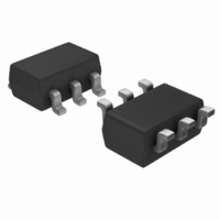
PIC10F222T-I/OT Microchip Technology, PIC10F222T-I/OT Datasheet - Page 18

PIC10F222T-I/OT
Manufacturer Part Number
PIC10F222T-I/OT
Description
IC PIC MCU FLASH 512X12 SOT23-6
Manufacturer
Microchip Technology
Series
PIC® 10Fr
Datasheets
1.PIC10F220-IMC.pdf
(6 pages)
2.PIC10F220-IMC.pdf
(86 pages)
3.PIC10F220-IMC.pdf
(6 pages)
4.PIC10F220-IMC.pdf
(18 pages)
Specifications of PIC10F222T-I/OT
Program Memory Type
FLASH
Program Memory Size
768B (512 x 12)
Package / Case
SOT-23-6
Core Processor
PIC
Core Size
8-Bit
Speed
8MHz
Peripherals
POR, WDT
Number Of I /o
3
Ram Size
23 x 8
Voltage - Supply (vcc/vdd)
2 V ~ 5.5 V
Data Converters
A/D 2x8b
Oscillator Type
Internal
Operating Temperature
-40°C ~ 85°C
Processor Series
PIC10F
Core
PIC
Data Bus Width
8 bit
Data Ram Size
23 B
Interface Type
USB
Maximum Clock Frequency
8 MHz
Number Of Programmable I/os
4
Number Of Timers
1
Maximum Operating Temperature
+ 85 C
Mounting Style
SMD/SMT
3rd Party Development Tools
52715-96, 52716-328, 52717-734
Development Tools By Supplier
PG164130, DV164035, DV244005, DV164005, PG164120
Minimum Operating Temperature
- 40 C
On-chip Adc
2-ch x 8-bit
Lead Free Status / RoHS Status
Lead free / RoHS Compliant
For Use With
AC162070 - HEADER INTRFC MPLAB ICD2 8/14PXLT06SOT - SOCKET TRAN ICE 6SOT W/CABLEAC163020 - ADAPTER PROGRAMMER PIC10F2XXAC164321 - MODULE SKT 6L PM3 SOT23AC164037 - MODULE SKT 6L PROMATE II SOT23
Eeprom Size
-
Connectivity
-
Lead Free Status / Rohs Status
Lead free / RoHS Compliant
Other names
PIC10F222T-I/OTTR
Available stocks
Company
Part Number
Manufacturer
Quantity
Price
Company:
Part Number:
PIC10F222T-I/OT
Manufacturer:
Microchip Technology
Quantity:
26 846
Part Number:
PIC10F222T-I/OT
Manufacturer:
MICROCHIP/微芯
Quantity:
20 000
PIC10F220/222
REGISTER 4-1:
DS41270E-page 16
bit 7
Legend:
R = Readable bit
-n = Value at POR
bit 7
bit 6
bit 5
bit 4
bit 3
bit 2
bit 1
bit 0
GPWUF
R/W-0
GPWUF: GPIO Reset bit
1 = Reset due to wake-up from Sleep on pin change
0 = After power-up or other Reset
Reserved: Do not use. Use of this bit may affect upward compatibility with future products.
Reserved: Do not use. Use of this bit may affect upward compatibility with future products.
TO: Time-out bit
1 = After power-up, CLRWDT instruction or SLEEP instruction
0 = A WDT time-out occurred
PD: Power-down bit
1 = After power-up or by the CLRWDT instruction
0 = By execution of the SLEEP instruction
Z: Zero bit
1 = The result of an arithmetic or logic operation is zero
0 = The result of an arithmetic or logic operation is not zero
DC: Digit carry/borrow bit (for ADDWF and SUBWF instructions)
ADDWF:
1 = A carry to the 4th low-order bit of the result occurred
0 = A carry to the 4th low-order bit of the result did not occur
SUBWF:
1 = A borrow from the 4th low-order bit of the result did not occur
0 = A borrow from the 4th low-order bit of the result occurred
C: Carry/borrow bit (for ADDWF, SUBWF and RRF, RLF instructions)
ADDWF:
1 = A carry occurred
0 = A carry did not occur
R/W-0
—
STATUS REGISTER (ADDRESS: 03h)
W = Writable bit
‘1’ = Bit is set
R/W-0
—
0 = A borrow occurred
SUBWF:
1 = A borrow did not occur Load bit with LSb or MSb, respectively
R-1
TO
U = Unimplemented bit, read as ‘0’
‘0’ = Bit is cleared
R-1
PD
RRF or RLF:
R/W-x
Z
© 2007 Microchip Technology Inc.
x = Bit is unknown
R/W-x
DC
R/W-x
C
bit 0


