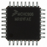
MCHC908MR8VFAE Freescale Semiconductor, MCHC908MR8VFAE Datasheet - Page 185

MCHC908MR8VFAE
Manufacturer Part Number
MCHC908MR8VFAE
Description
IC MCU 8K FLASH 8MHZ PWM 32-LQFP
Manufacturer
Freescale Semiconductor
Series
HC08r
Datasheet
1.MCHC908MR8VFAE.pdf
(372 pages)
Specifications of MCHC908MR8VFAE
Core Processor
HC08
Core Size
8-Bit
Speed
8MHz
Connectivity
SCI
Peripherals
LVD, POR, PWM
Number Of I /o
16
Program Memory Size
8KB (8K x 8)
Program Memory Type
FLASH
Ram Size
256 x 8
Voltage - Supply (vcc/vdd)
4.5 V ~ 5.5 V
Data Converters
A/D 7x10b
Oscillator Type
Internal
Operating Temperature
-40°C ~ 105°C
Package / Case
32-LQFP
Processor Series
HC08MR
Core
HC08
Data Bus Width
8 bit
Data Ram Size
512 B
Interface Type
SCI, SPI
Maximum Clock Frequency
8 MHz
Number Of Programmable I/os
33
Number Of Timers
4
Maximum Operating Temperature
+ 105 C
Mounting Style
SMD/SMT
Development Tools By Supplier
FSICEBASE, M68CBL05CE
Minimum Operating Temperature
- 40 C
On-chip Adc
8 bit, 8 Channel
Lead Free Status / RoHS Status
Lead free / RoHS Compliant
Eeprom Size
-
Lead Free Status / Rohs Status
Details
Available stocks
Company
Part Number
Manufacturer
Quantity
Price
Company:
Part Number:
MCHC908MR8VFAE
Manufacturer:
Freescale
Quantity:
8 393
Company:
Part Number:
MCHC908MR8VFAE
Manufacturer:
Freescale Semiconductor
Quantity:
10 000
- Current page: 185 of 372
- Download datasheet (4Mb)
9.13 PWM Glossary
MC68HC908MR8 — Rev 4.1
Freescale Semiconductor
OUT6:OUT1— PWM Pin Output Control Bits
CPU Cycle — One internal bus cycle (1/f
PWM Clock Cycle (or Period) — One tick of the PWM counter (1/f
with no prescaler). See
PWM Cycle (or Period)
OUTx Bit
Pulse-Width Modulator for Motor Control (PWMMC)
OUT1
OUT2
OUT3
OUT4
OUT5
OUT6
These read/write bits control the PWM pins according to
•
•
Center-aligned mode: The time it takes the PWM counter to count
up and count down (modulus * 2/f
Figure
Edge-aligned mode: The time it takes the PWM counter to count
up (modulus/f
1 — PWM1 is active
0 — PWM1 is inactive
1 — PWM2 is complement of PWM 1
0 — PWM2 is inactive
1 — PWM3 is active
0 — PWM3 is inactive
1 — PWM4 is complement of PWM 3
0 — PWM4 is inactive
1 — PWM5 is active
0 — PWM5 is inactive
1 — PWM 6 is complement of PWM 5
0 — PWM6 is inactive
9-43.
Complementary Mode
OP
). See
Figure
Table 9-7. OUTx Bits
Pulse-Width Modulator for Motor Control (PWMMC)
Figure
9-43.
9-43.
OP
OP
assuming no prescaler). See
1 — PWM1 is active
0 — PWM1 is inactive
1 — PWM2 is active
0 — PWM2 is inactive
1 — PWM3 is active
0 — PWM3 is inactive
1 — PWM4 is active
0 — PWM4 is inactive
1 — PWM5 is active
0 — PWM5 is inactive
1 — PWM6 is active
0 — PWM6 is inactive
)
Independent Mode
PWM Glossary
Technical Data
Table
9-7.
OP
185
Related parts for MCHC908MR8VFAE
Image
Part Number
Description
Manufacturer
Datasheet
Request
R
Part Number:
Description:
Manufacturer:
Freescale Semiconductor, Inc
Datasheet:
Part Number:
Description:
Manufacturer:
Freescale Semiconductor, Inc
Datasheet:
Part Number:
Description:
Manufacturer:
Freescale Semiconductor, Inc
Datasheet:
Part Number:
Description:
Manufacturer:
Freescale Semiconductor, Inc
Datasheet:
Part Number:
Description:
Manufacturer:
Freescale Semiconductor, Inc
Datasheet:
Part Number:
Description:
Manufacturer:
Freescale Semiconductor, Inc
Datasheet:
Part Number:
Description:
Manufacturer:
Freescale Semiconductor, Inc
Datasheet:
Part Number:
Description:
Manufacturer:
Freescale Semiconductor, Inc
Datasheet:
Part Number:
Description:
Manufacturer:
Freescale Semiconductor, Inc
Datasheet:
Part Number:
Description:
Manufacturer:
Freescale Semiconductor, Inc
Datasheet:
Part Number:
Description:
Manufacturer:
Freescale Semiconductor, Inc
Datasheet:
Part Number:
Description:
Manufacturer:
Freescale Semiconductor, Inc
Datasheet:
Part Number:
Description:
Manufacturer:
Freescale Semiconductor, Inc
Datasheet:
Part Number:
Description:
Manufacturer:
Freescale Semiconductor, Inc
Datasheet:
Part Number:
Description:
Manufacturer:
Freescale Semiconductor, Inc
Datasheet:


