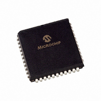
PIC16C74A-20/L Microchip Technology, PIC16C74A-20/L Datasheet - Page 3

PIC16C74A-20/L
Manufacturer Part Number
PIC16C74A-20/L
Description
IC MCU OTP 4KX14 A/D PWM 44PLCC
Manufacturer
Microchip Technology
Series
PIC® 16Cr
Datasheets
1.PIC16F616T-ISL.pdf
(8 pages)
2.PIC16F818-ISO.pdf
(6 pages)
3.PIC16C72-04SO.pdf
(289 pages)
4.PIC16LC74A-04P.pdf
(8 pages)
Specifications of PIC16C74A-20/L
Core Size
8-Bit
Program Memory Size
7KB (4K x 14)
Core Processor
PIC
Speed
20MHz
Connectivity
I²C, SPI, UART/USART
Peripherals
Brown-out Detect/Reset, POR, PWM, WDT
Number Of I /o
33
Program Memory Type
OTP
Ram Size
192 x 8
Voltage - Supply (vcc/vdd)
4 V ~ 6 V
Data Converters
A/D 8x8b
Oscillator Type
External
Operating Temperature
0°C ~ 70°C
Package / Case
44-PLCC
Controller Family/series
PIC16C
No. Of I/o's
33
Ram Memory Size
192Byte
Cpu Speed
10MHz
No. Of Timers
3
Interface
I2C, SPI, USART
Embedded Interface Type
I2C, SPI, USART
Rohs Compliant
Yes
Lead Free Status / RoHS Status
Lead free / RoHS Compliant
For Use With
AC164309 - MODULE SKT FOR PM3 44PLCC444-1001 - DEMO BOARD FOR PICMICRO MCUDVA16XL441 - ADAPTER DEVICE ICE 44PLCCDV007003 - PROGRAMMER UNIVERSAL PROMATE II
Eeprom Size
-
Lead Free Status / RoHS Status
Lead free / RoHS Compliant, Lead free / RoHS Compliant
Available stocks
Company
Part Number
Manufacturer
Quantity
Price
Company:
Part Number:
PIC16C74A-20/L
Manufacturer:
Microchip Technology
Quantity:
10 000
7. Module: Timer1
EXAMPLE 2:
EXAMPLE 3:
EXAMPLE 4:
2001 Microchip Technology Inc.
The Timer1 value may unexpectedly increment if
either the TMR1H, or the TMR1L register is writ-
ten. If Timer1 is ON and then turned OFF, perform-
ing any write instruction with TMR1H as the
destination, may cause TMR1L to increment.
If Timer1 is ON and then turned OFF when
TMR1H:TMR1L = xx:FF, performing any write
instruction with TMR1L as the destination may
cause TMR1H to increment.
Work around
To preserve Timer1 register values:
a) Read Timer1 register values into “shadow”
b) Perform any write instruction(s) on the
c) Write the shadow register values back into
BSF T1CON, TMR1ON
BCF T1CON, TMR1ON
MOVF TMR1H, 1
TMR1 value before MOVF instruction:
TMR1 value after MOVF instruction:
BSF T1CON, TMR1ON
BCF T1CON, TMR1ON
CLRF TMR1L
TMR1 value before CLRF instruction:
TMR1 value after CLRF instruction:
(TMR1IF is not set.)
BSF T1CON, TMR1ON
BCF T1CON, TMR1ON
MOVF TMR1H, 1
TMR1 value before MOVF instruction:
TMR1 value after MOVF instruction:
registers.
shadow registers.
the Timer1 registers.
TMR1H:TMR1L = FF:FF
TMR1H:TMR1L = FF:00
TMR1H:TMR1L = FF:FF
TMR1H:TMR1L = 00:00
TMR1H:TMR1L = 3F:00
TMR1H:TMR1L = 3F:01
:
:
TMR1L INCREMENT
(CASE 1)
TMR1L INCREMENT
(CASE 2)
TMR1H INCREMENT
8. Module: USART
When the USART (SCI) is configured in Asynchro-
nous mode with the BRGH bit set, a high number
of receive errors may be experienced. For asyn-
chronous receive operations, it is recommended
that the USART be configured with the BRGH bit
cleared.
PIC16C74A
DS80089A-page 3


