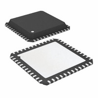
AT32UC3B1256-Z1UT Atmel, AT32UC3B1256-Z1UT Datasheet - Page 80

AT32UC3B1256-Z1UT
Manufacturer Part Number
AT32UC3B1256-Z1UT
Description
IC MCU AVR32 256KB FLASH 48-QFN
Manufacturer
Atmel
Series
AVR®32 UC3r
Datasheet
1.AT32UC3B164-Z1UT.pdf
(105 pages)
Specifications of AT32UC3B1256-Z1UT
Core Processor
AVR
Core Size
32-Bit
Speed
60MHz
Connectivity
I²C, IrDA, SPI, SSC, UART/USART, USB
Peripherals
Brown-out Detect/Reset, DMA, POR, PWM, WDT
Number Of I /o
28
Program Memory Size
256KB (256K x 8)
Program Memory Type
FLASH
Ram Size
32K x 8
Voltage - Supply (vcc/vdd)
1.65 V ~ 1.95 V
Data Converters
A/D 6x10b
Oscillator Type
Internal
Operating Temperature
-40°C ~ 85°C
Package / Case
48-QFN Exposed Pad
For Use With
ATSTK600-TQFP48 - STK600 SOCKET/ADAPTER 48-TQFPATAVRONEKIT - KIT AVR/AVR32 DEBUGGER/PROGRMMR770-1008 - ISP 4PORT ATMEL AVR32 MCU SPIATEVK1101 - KIT DEV/EVAL FOR AVR32 AT32UC3B
Lead Free Status / RoHS Status
Lead free / RoHS Compliant
Eeprom Size
-
12.2.2
32059K–03/2011
Rev. G
- PWM
- SPI
1. PWM channel interrupt enabling triggers an interrupt
2. PWN counter restarts at 0x0001
3. PWM update period to a 0 value does not work
1. SPI Slave / PDCA transfer: no TX UNDERRUN flag
2. SPI Bad Serial Clock Generation on 2nd chip_select when SCBR = 1, CPOL=1 and
3. SPI Glitch on RXREADY flag in slave mode when enabling the SPI or during the first
When enabling a PWM channel that is configured with center aligned period (CALG=1), an
interrupt is signalled.
Fix/Workaround
When using center aligned mode, enable the channel and read the status before channel
interrupt is enabled.
The PWM counter restarts at 0x0001 and not 0x0000 as specified. Because of this the first
PWM period has one more clock cycle.
Fix/Workaround
- The first period is 0x0000, 0x0001, ..., period.
- Consecutive periods are 0x0001, 0x0002, ..., period.
It is impossible to update a period equal to 0 by the using the PWM update register
(PWM_CUPD).
Fix/Workaround
Do not update the PWM_CUPD register with a value equal to 0.
There is no TX UNDERRUN flag available, therefore in SPI slave mode, there is no way to
be informed of a character lost in transmission.
Fix/Workaround
For PDCA transfer: none.
NCPHA=0
When multiple CS are in use, if one of the baudrate equals to 1 and one of the others doesn't
equal to 1, and CPOL=1 and CPHA=0, then an aditional pulse will be generated on SCK.
Fix/Workaround
When multiple CS are in use, if one of the baudrate equals 1, the other must also equal 1 if
CPOL=1 and CPHA=0.
transfer
In slave mode, the SPI can generate a false RXREADY signal during enabling of the SPI or
during the first transfer.
Fix/Workaround
1. Set slave mode, set required CPOL/CPHA.
2. Enable SPI.
3. Set the polarity CPOL of the line in the opposite value of the required one.
4. Set the polarity CPOL to the required one.
5. Read the RXHOLDING register.
Transfers can now befin and RXREADY will now behave as expected.
AT32UC3B
80


