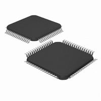
DSPIC33FJ32GS406-I/PT Microchip Technology, DSPIC33FJ32GS406-I/PT Datasheet - Page 2

DSPIC33FJ32GS406-I/PT
Manufacturer Part Number
DSPIC33FJ32GS406-I/PT
Description
IC MCU/DSP 32KB FLASH 64TQFP
Manufacturer
Microchip Technology
Series
dsPIC™ 33Fr
Specifications of DSPIC33FJ32GS406-I/PT
Core Processor
dsPIC
Core Size
16-Bit
Speed
40 MIPs
Connectivity
I²C, IrDA, LIN, SCI, SPI, UART/USART, USB
Peripherals
Brown-out Detect/Reset, QEI, POR, PWM, WDT
Number Of I /o
58
Program Memory Size
32KB (32K x 8)
Program Memory Type
FLASH
Ram Size
4K x 8
Voltage - Supply (vcc/vdd)
3 V ~ 3.6 V
Data Converters
A/D 16x10b
Oscillator Type
Internal
Operating Temperature
-40°C ~ 85°C
Package / Case
64-TFQFP
Core Frequency
40MHz
Embedded Interface Type
I2C, SPI, UART
No. Of I/o's
53
Flash Memory Size
32KB
Supply Voltage Range
3V To 3.6V
Rohs Compliant
Yes
Lead Free Status / RoHS Status
Lead free / RoHS Compliant
Eeprom Size
-
Lead Free Status / RoHS Status
Lead free / RoHS Compliant, Lead free / RoHS Compliant
Available stocks
Company
Part Number
Manufacturer
Quantity
Price
Company:
Part Number:
DSPIC33FJ32GS406-I/PT
Manufacturer:
Microchip Technology
Quantity:
10 000
dsPIC33FJ32GS406/606/608/610 and dsPIC33FJ64GS406/606/608/610
TABLE 2:
DS80489C-page 2
Note 1:
Reserved
Interrupts
Module
ECAN
Speed
ECAN
JTAG
PWM
PWM
PWM
ADC
High
SPI
Only those issues indicated in the last column apply to the current silicon revision.
Synchronization
Consumption in
Boundary Scan
External Period
Exit from Doze
Error Interrupt
PWM Module
Master Time
Sleep Mode
Reset Mode
Secondary
WAKIF bit
ASS1 Pin
(XPRES)
Mode on
Interrupt
Feature
SILICON ISSUE SUMMARY
Current
Enable
Base
Flag
—
Number
Item
10.
1.
2.
3.
4.
5.
6.
7.
8.
9.
The WAKIF bit in the CxINTF register cannot be
cleared by software instruction after the device is
interrupted from Sleep due to activity on the CAN
bus.
The ASS1 pin function does not work.
The boundary scan cells for the RD3 and RD13 pins
are swapped.
The external time base synchronization output pin,
SYNCO2, does not work.
An interrupt with a priority level lower than the CPU
priority level will trigger the dsPIC
exit the Doze mode, but an interrupt request will not
be generated.
If the ADC module is in an enabled state when the
device enters Sleep mode, the power-down current
(I
sheet specifications.
When using the External Period Reset mode, PWM
period will get reset immediately if the Reset signal
is active at the end of the PWM ON time.
A glitch may be observed on the PWM pins when
the PWM module is enabled after assignment of pin
ownership to the PWM module.
The ERRIF status bit does not get set when a CAN
error condition occurs.
PD
) of the device may exceed the device data
Issue Summary
—
®
DSC device to
© 2010 Microchip Technology Inc.
Affected Revisions
A0
—
X
X
X
X
X
X
X
X
X
(1)


