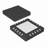
PIC18F13K50-I/MQ Microchip Technology, PIC18F13K50-I/MQ Datasheet - Page 240

PIC18F13K50-I/MQ
Manufacturer Part Number
PIC18F13K50-I/MQ
Description
IC PIC MCU FLASH 512KX8 20-QFN
Manufacturer
Microchip Technology
Series
PIC® XLP™ 18Fr
Datasheets
1.PIC18F13K50-ISS.pdf
(420 pages)
2.PIC18F13K50-ISS.pdf
(40 pages)
3.PIC18F13K50-ISS.pdf
(10 pages)
4.PIC18F13K50-ISS.pdf
(2 pages)
5.PIC18F14K50-IP.pdf
(422 pages)
Specifications of PIC18F13K50-I/MQ
Program Memory Type
FLASH
Program Memory Size
8KB (4K x 16)
Package / Case
20-QFN
Core Processor
PIC
Core Size
8-Bit
Speed
48MHz
Connectivity
I²C, SPI, UART/USART, USB
Peripherals
Brown-out Detect/Reset, POR, PWM, WDT
Number Of I /o
14
Eeprom Size
256 x 8
Ram Size
512 x 8
Voltage - Supply (vcc/vdd)
1.8 V ~ 5.5 V
Data Converters
A/D 11x10b
Oscillator Type
Internal
Operating Temperature
-40°C ~ 85°C
Processor Series
PIC18F
Core
PIC
Data Bus Width
8 bit
Data Ram Size
512 B
Interface Type
EUSART/I2C/MSSP/SPI/USB
Maximum Clock Frequency
48 MHz
Number Of Programmable I/os
15
Number Of Timers
4
Operating Supply Voltage
1.8 V to 5.6 V
Maximum Operating Temperature
+ 85 C
Mounting Style
SMD/SMT
3rd Party Development Tools
52715-96, 52716-328, 52717-734, 52712-325, EWPIC18
Development Tools By Supplier
PG164130, DV164035, DV244005, DV164005, DM164127, DV164126
Minimum Operating Temperature
- 40 C
On-chip Adc
11-ch x 10-bit
Lead Free Status / RoHS Status
Lead free / RoHS Compliant
For Use With
DV164126 - KIT DEVELOPMENT USB W/PICKIT 2DM164127 - KIT DEVELOPMENT USB 18F14/13K50
Lead Free Status / Rohs Status
Lead free / RoHS Compliant
Available stocks
Company
Part Number
Manufacturer
Quantity
Price
Part Number:
PIC18F13K50-I/MQ
Manufacturer:
MICROCHIP/微芯
Quantity:
20 000
- PIC18F13K50-ISS PDF datasheet
- PIC18F13K50-ISS PDF datasheet #2
- PIC18F13K50-ISS PDF datasheet #3
- PIC18F13K50-ISS PDF datasheet #4
- PIC18F14K50-IP PDF datasheet #5
- Current page: 240 of 420
- Download datasheet (4Mb)
PIC18F/LF1XK50
19.5.3
Exiting Sleep and Idle modes by Reset causes code
execution to restart at address 0. See
“Reset”
The exit delay time from Reset to the start of code
execution depends on both the clock sources before
and after the wake-up and the type of oscillator. Exit
delays are summarized in
TABLE 19-2:
DS41350E-page 240
Note 1:
T1OSC or LFINTOSC
Primary Device Clock
2:
3:
4:
(PRI_IDLE mode)
before Wake-up
for more details.
Clock Source
HFINTOSC
(Sleep mode)
T
required delays (see
Includes both the HFINTOSC 16 MHz source and postscaler derived frequencies.
T
Execution continues during the HFINTOSC stabilization period, T
EXIT BY RESET
CSD
OST
None
is a required delay when waking from Sleep and all Idle modes and runs concurrently with any other
is the Oscillator Start-up Timer. t
EXIT DELAY ON WAKE-UP BY RESET FROM SLEEP MODE OR ANY IDLE MODE
(BY CLOCK SOURCES)
(2)
Table
(1)
19-2.
Section 19.4 “Idle
Section 23.0
after Wake-up
Clock Source
HFINTOSC
HFINTOSC
HFINTOSC
HFINTOSC
LP, XT, HS
LP, XT, HS
LP, XT, HS
LP, XT, HS
EC, RC
EC, RC
EC, RC
EC, RC
HSPLL
HSPLL
HSPLL
HSPLL
PLL
Preliminary
Modes”). On Reset, HFINTOSC defaults to 1 MHz.
is the PLL Lock-out Timer (parameter F12).
(2)
(1)
(1)
(1)
19.5.4
Certain exits from power-managed modes do not
invoke the OST at all. There are two cases:
• PRI_IDLE mode, where the primary clock source
• the primary clock source is not any of the LP, XT,
In these instances, the primary clock source either
does not require an oscillator start-up delay since it is
already running (PRI_IDLE), or normally does not
require an oscillator start-up delay (RC, EC, INTOSC,
and INTOSCIO modes). However, a fixed delay of
interval T
when leaving Sleep and Idle modes to allow the CPU
to prepare for execution. Instruction execution resumes
on the first clock cycle following this delay.
is not stopped and
HS or HSPLL modes.
CSD
T
T
T
OST
OST
OST
Exit Delay
EXIT WITHOUT AN OSCILLATOR
START-UP DELAY
T
T
T
T
T
T
T
T
T
IOBST
IOBST
IOBST
following the wake event is still required
None
CSD
CSD
CSD
CSD
OST
OST
OST
+ t
+ t
+ t
(1)
(3)
PLL
(1)
(4)
PLL
(1)
(3)
PLL
(1)
.
(4)
(4)
(3)
(3)
(3)
2010 Microchip Technology Inc.
Clock Ready Status
Bit (OSCCON)
OSTS
OSTS
OSTS
OSTS
IOSF
IOSF
IOSF
IOSF
Related parts for PIC18F13K50-I/MQ
Image
Part Number
Description
Manufacturer
Datasheet
Request
R

Part Number:
Description:
Manufacturer:
Microchip Technology Inc.
Datasheet:

Part Number:
Description:
Manufacturer:
Microchip Technology Inc.
Datasheet:

Part Number:
Description:
Manufacturer:
Microchip Technology Inc.
Datasheet:

Part Number:
Description:
Manufacturer:
Microchip Technology Inc.
Datasheet:

Part Number:
Description:
Manufacturer:
Microchip Technology Inc.
Datasheet:

Part Number:
Description:
Manufacturer:
Microchip Technology Inc.
Datasheet:

Part Number:
Description:
Manufacturer:
Microchip Technology Inc.
Datasheet:

Part Number:
Description:
Manufacturer:
Microchip Technology Inc.
Datasheet:


