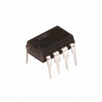
ATTINY13A-PU Atmel, ATTINY13A-PU Datasheet - Page 119

ATTINY13A-PU
Manufacturer Part Number
ATTINY13A-PU
Description
IC MCU AVR 1K FLASH 20MHZ 8PDIP
Manufacturer
Atmel
Series
AVR® ATtinyr
Specifications of ATTINY13A-PU
Core Processor
AVR
Core Size
8-Bit
Speed
20MHz
Peripherals
Brown-out Detect/Reset, POR, PWM, WDT
Number Of I /o
6
Program Memory Size
1KB (512 x 16)
Program Memory Type
FLASH
Eeprom Size
64 x 8
Ram Size
64 x 8
Voltage - Supply (vcc/vdd)
1.8 V ~ 5.5 V
Data Converters
A/D 4x10b
Oscillator Type
Internal
Operating Temperature
-40°C ~ 85°C
Package / Case
8-DIP (0.300", 7.62mm)
Processor Series
ATTINY1x
Core
AVR8
Data Bus Width
8 bit
Data Ram Size
64 B
Interface Type
SPI
Maximum Clock Frequency
20 MHz
Number Of Programmable I/os
6
Number Of Timers
1
Maximum Operating Temperature
+ 85 C
Mounting Style
Through Hole
3rd Party Development Tools
EWAVR, EWAVR-BL
Development Tools By Supplier
ATAVRDRAGON, ATSTK500, ATSTK600, ATAVRISP2, ATAVRONEKIT, ATAKSTK511
Minimum Operating Temperature
- 40 C
On-chip Adc
10 bit, 4 Channel
Cpu Family
ATtiny
Device Core
AVR
Device Core Size
8b
Frequency (max)
20MHz
Total Internal Ram Size
64Byte
# I/os (max)
6
Number Of Timers - General Purpose
1
Operating Supply Voltage (typ)
2.5/3.3/5V
Operating Supply Voltage (max)
5.5V
Operating Supply Voltage (min)
1.8V
Instruction Set Architecture
RISC
Operating Temp Range
-40C to 85C
Operating Temperature Classification
Industrial
Mounting
Through Hole
Pin Count
8
Package Type
PDIP
Package
8PDIP
Family Name
ATtiny
Maximum Speed
20 MHz
Operating Supply Voltage
2.5|3.3|5 V
For Use With
ATSTK600-DIP40 - STK600 SOCKET/ADAPTER 40-PDIP770-1007 - ISP 4PORT ATMEL AVR MCU SPI/JTAGATAVRDRAGON - KIT DRAGON 32KB FLASH MEM AVRATAVRISP2 - PROGRAMMER AVR IN SYSTEMATJTAGICE2 - AVR ON-CHIP D-BUG SYSTEM
Lead Free Status / RoHS Status
Lead free / RoHS Compliant
Connectivity
-
Lead Free Status / Rohs Status
Lead free / RoHS Compliant
Available stocks
Company
Part Number
Manufacturer
Quantity
Price
18.4
18.4.1
Table 18-2.
18.4.2
Table 18-3.
8126E–AVR–07/10
Calibration
Method
Factory
Calibration
User
Calibration
Symbol
1/t
t
t
t
t
t
Δ
CLCL
CHCX
CLCX
CLCH
CHCL
t
CLCL
CLCL
Clock Characteristics
Calibrated Internal RC Oscillator Accuracy
External Clock Drive
Parameter
Clock Frequency
Clock Period
High Time
Low Time
Rise Time
Fall Time
Change in period from one clock cycle to the next
Calibration Accuracy of Internal RC Oscillator
External Clock Drive
4 – 5 MHz / 8 – 10 MHz
Fixed frequency within:
Target Frequency
It is possible to manually calibrate the internal oscillator to be more accurate than default factory
calibration. Note that the oscillator frequency depends on temperature and voltage. Voltage and
temperature characteristics can be found in
154,
ure 19-64 on page
Notes:
Figure 18-2. External Clock Drive Waveform
4.8 / 9.6 MHz
Figure 19-61 on page
1. Accuracy of oscillator frequency at calibration point (fixed temperature and fixed voltage).
V
IL1
V
IH1
156.
Fixed voltage within:
1.8 – 5.5V
155,
V
3V
CC
Figure 19-62 on page
V
Min.
250
100
100
CC
0
= 1.8 - 5.5V
Max.
2.0
2.0
Figure 19-59 on page
4
2
Fixed temperature
-40°C to +85°C
Temperature
V
within:
Min.
25°C
100
CC
40
40
155,
0
= 2.7 - 5.5V
Figure 19-63 on page
Max.
1.6
1.6
10
2
154,
Accuracy at given Voltage
V
Min.
CC
50
20
20
0
Figure 19-60 on page
& Temperature
= 4.5 - 5.5V
±10%
±2%
Max.
0.5
0.5
20
2
156, and
(1)
Units
MHz
ns
ns
ns
µs
µs
%
Fig-
119


