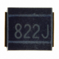
NL565050T-822J-PF TDK Corporation, NL565050T-822J-PF Datasheet - Page 2

NL565050T-822J-PF
Manufacturer Part Number
NL565050T-822J-PF
Description
INDUCTOR 8.2MH 28MA 5% 2220
Manufacturer
TDK Corporation
Series
NLr
Datasheet
1.NL565050T-682J-PF.pdf
(2 pages)
Specifications of NL565050T-822J-PF
Inductance
8.2mH
Tolerance
±5%
Current
28mA
Dc Resistance (dcr)
125 Ohm Max
Q @ Freq
30 @ 252kHz
Self Resonant Freq
600kHz
Package / Case
2220 (5650 Metric)
Mounting Type
Surface Mount
Operating Temperature
-40°C ~ 105°C
Frequency - Test
252kHz
Applications
Signal Line
Maximum Dc Current
28 mAmps
Maximum Dc Resistance
125 Ohms
Q Minimum
30
Termination Style
SMD/SMT
Dimensions
5 mm W x 5.6 mm L x 5 mm H
Shielding
Unshielded
Lead Free Status / RoHS Status
Lead free / RoHS Compliant
Current - Saturation
-
Current - Temperature Rise
-
Lead Free Status / RoHS Status
Lead free / RoHS Compliant, Lead free / RoHS Compliant
Other names
445-3665-2
Available stocks
Company
Part Number
Manufacturer
Quantity
Price
Part Number:
NL565050T-822J-PF
Manufacturer:
TDK/东电化
Quantity:
20 000
SHAPES AND DIMENSIONS/RECOMMENDED PC BOARD PATTERN
ELECTRICAL CHARACTERISTICS
Inductance
(mH)
1.2
1.5
1.8
2.2
2.7
3.3
3.9
4.7
5.6
6.8
8.2
10
∗
• Test equipment L, Q: YHP4194A IMPEDANCE ANALYZER (16085A+16093B+TDK TF-1)
TYPICAL ELECTRICAL CHARACTERISTICS
INDUCTANCE CHANGE vs. DC
SUPERPOSITION CHARACTERISTICS
• All specifications are subject to change without notice.
Terminal
electrode
100
Rated current: Value obtained when current flows and the temperature has risen to 20°C or when DC current flows and the initial value of inductance has
fallen by 10%, whichever is smaller.
0.5
50
10
5
1
10
10mH
1.2mH
5.6mH
2.7mH
Test circuit
5.6±0.3
472J
( 0.5 )
DC
DC current ( mA )
Inductance
tolerance
±5%
±5%
±5%
±5%
±5%
±5%
±5%
±5%
±5%
±5%
±5%
±5%
SRF: HP8753C NETWORK ANALYZER (Zin=Zout=50Ω)
Rdc: MATSUSHITA VP-2941A DIGITAL MILLIOHM METER
A
YHP model-4275A
Specimen
50
L=5H C=20000μF
or equivalent
100
5±0.3
4±0.2
Q
min.
30
30
30
30
30
30
30
30
30
30
30
20
500
C1
Test frequency
L, Q (MHz)
0.252
0.252
0.252
0.252
0.252
0.252
0.252
0.252
0.252
0.252
0.252
0.0796
Weight: 380mg
INDUCTANCE CHANGE vs.
TEMPERATURE CHARACTERISTICS
–2
–4
4
2
0
YHP 4194A IMPEDANCE ANALYZER
at 10kHz 0.5V
–40 – 20
Self-resonant
frequency (MHz)min.
1.5
1.4
1.3
1.2
1.1
1
1
0.9
0.8
0.7
0.6
0.5
2.2mH
Temperature ( ˚C )
0
2
20
4
40
2
Inductor
Pattern
60
DC resistance
(Ω)max.
17
20
30
35
55
60
70
78
85
110
125
150
80
Dimensions in mm
100
Rated current
(mA)max.
75
70
60
55
45
40
38
36
33
30
28
25
Q vs. FREQUENCY
CHARACTERISTICS
100
80
60
40
20
0
Test equipment:Q meter model-4343B, YHP
002-07 / 20090706 / e511_nl5650.fm
0.1
∗
10mH
5.6mH
0.5
Frequency ( MHz )
3.3mH
Part No.
NL565050T-122J-PF
NL565050T-152J-PF
NL565050T-182J-PF
NL565050T-222J-PF
NL565050T-272J-PF
NL565050T-332J-PF
NL565050T-392J-PF
NL565050T-472J-PF
NL565050T-562J-PF
NL565050T-682J-PF
NL565050T-822J-PF
NL565050T-103J-PF
1.8mH
1
5
10
(2/2)


