B78108S1823J EPCOS Inc, B78108S1823J Datasheet - Page 14
B78108S1823J
Manufacturer Part Number
B78108S1823J
Description
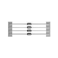
CHOKE RF 82UH 390MA AXIAL
Manufacturer
EPCOS Inc
Series
BCr
Type
Ferrite Corer
Specifications of B78108S1823J
Inductance
82µH
Tolerance
±5%
Current
390mA
Dc Resistance (dcr)
1.540 Ohm Max
Q @ Freq
35 @ 2.52MHz
Self Resonant Freq
6MHz
Package / Case
Axial
Mounting Type
Through Hole
Frequency - Test
2.52MHz
Material - Core
Ferrite Drum
Applications
General Purpose
Dimensions
4 mm Dia. x 53 mm L
Test Frequency
2.52 MHz
Maximum Dc Current
390 mA
Maximum Dc Resistance
1.54 Ohms
Self Resonant Frequency
6 MHz
Q Minimum
35
Operating Temperature Range
- 55 C to + 125 C
Termination Style
Axial
Inductance Tolerance
± 5%
Dc Resistance Max
1.54ohm
Dc Current Rating
390mA
Q Test Frequency
2.52MHz
Inductor Case Style
Axial Leaded
No. Of Pins
2
Svhc
No SVHC (18-Jun-2010)
Rohs Compliant
Yes
Body Diameter
4mm
Lead Free Status / RoHS Status
Lead free / RoHS Compliant
Shielding
-
Current - Saturation
-
Current - Temperature Rise
-
Lead Free Status / Rohs Status
Lead free / RoHS Compliant
Other names
B78108S1823J000
Available stocks
Company
Part Number
Manufacturer
Quantity
Price

Part Number:
B78108S1823J000
Manufacturer:
EPCOS/爱普科斯
Quantity:
20 000


7
7.1
The rated voltage V
component at temperatures between the lower category temperature T
temperature T
7.2
The test voltage V
test duration in the course of final inspection (100% end of line testing). This test may be repeated
once as an incoming goods inspection test.
7.3
The rated current l
the nominal operating conditions.
For components with 1, 2 or 3 lines, the rated current is specified for simultaneous flow of a current
of this value through all lines.
During ac operation, higher thermal loads may be caused due to waveforms which deviate from a
pure sine wave. Where necessary, such cases must be taken into consideration.
7.4
The rated current may be exceeded briefly. Details on permissible currents and load duration can
be obtained upon request.
7.5
Saturation effects (e.g in the ferrite cores used) may occur when high-energy pulses are applied to
the components and these may lead to impaired interference suppression. The maximum permis-
sible voltage-time integral area is used to characterize the pulse handling capability of chokes. For
standard components a range from 1 to 10 mVs can be assumed. More specific data can be ob-
tained upon request.
7.6
At ambient temperatures above the operating temperature stated in the data sheet, the operating
current must be reduced according to the derating curve.
7.7
The rated inductance L
measured at the frequency f
General Technical Information
Electrical characteristics
Rated voltage V
Test voltage V
Rated current I
Overcurrent
Pulse handling capability
Current derating I
Rated inductance L
max
.
T
R
is the ac or dc voltage which may be applied to the component for the specified
is ac or dc current at which the component may be continuously operated under
R
is the maximum ac or dc voltage which can be continuously applied to the
T
R
R
R
is the inductance which has been used to designate the choke, as
op
L
.
R
/ I
R
22
04/00
min
and the upper category
Related parts for B78108S1823J
Image
Part Number
Description
Manufacturer
Datasheet
Request
R


Part Number:
Description:
CAP .15UF 63V METAL POLY
Manufacturer:
EPCOS Inc
Datasheet:


Part Number:
Description:
CAP .01UF 400V METAL POLY
Manufacturer:
EPCOS Inc
Datasheet:
