VLP5610T-4R7MR90 TDK Corporation, VLP5610T-4R7MR90 Datasheet
VLP5610T-4R7MR90
Manufacturer Part Number
VLP5610T-4R7MR90
Description
INDUCTOR POWER 4.7UH 20% SMD
Manufacturer
TDK Corporation
Series
VLPr
Type
Drum Corer
Datasheet
1.VLP5610T-100MR65.pdf
(2 pages)
Specifications of VLP5610T-4R7MR90
Inductance
4.7µH
Tolerance
±20%
Package / Case
0.220" L x 0.197" W x 0.039" H (5.60mm x 5.00mm x 1.00mm)
Current
900mA
Current - Saturation
1.08A
Current - Temperature Rise
900mA
Dc Resistance (dcr)
240 mOhm Max
Mounting Type
Surface Mount
Frequency - Test
100kHz
Applications
Power Line
Test Frequency
100 KHz
Maximum Dc Current
0.9 Amp
Maximum Dc Resistance
0.24 Ohms
Dimensions
5 mm W x 5.6 mm L x 1 mm H
Shielding
Unshielded
Termination Style
SMD/SMT
Lead Free Status / RoHS Status
Lead free / RoHS Compliant
Q @ Freq
-
Self Resonant Freq
-
Lead Free Status / Rohs Status
Lead free / RoHS Compliant
Other names
445-1929-2
Available stocks
Company
Part Number
Manufacturer
Quantity
Price
Company:

Part Number:
VLP5610T-4R7MR90
Manufacturer:
TDK
Quantity:
192 000


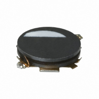
SMD Inductors(Coils)
For Power Line(Wound)
VLP Series VLP5610
FEATURES
• This is an SMD power inductor for power supplies that has an
• User terminals are contact-formed on the bottom of the drum
• It uses crosswise windings and supports large currents.
• It is lead-free compatible.
• With several variations in drum core height, users can choose
APPLICATIONS
• LCD modules
• Cellular phones
• Hard disk drives
SHAPES AND DIMENSIONS
ELECTRICAL CHARACTERISTICS
Part No.
VLP5610T-2R7M1R0
VLP5610T-4R7MR90
VLP5610T-6R8MR80
VLP5610T-100MR65
VLP5610T-150MR52
VLP5610T-220MR45
VLP5610T-330MR36
VLP5610T-470MR29
∗
• Conformity to RoHS Directive: This means that, in conformity with EU Directive 2002/95/EC, lead, cadmium, mercury, hexavalent chromium, and specific
• All specifications are subject to change without notice.
Rated current:The rated current is the smaller of the values given based on the rate of inductance change (10% decrease from the initial value) or the
bromine-based flame retardants, PBB and PBDE, have not been used, except for exempted applications.
open magnetic path construction based on a low-height drum
core (upright).
core using copper (finished with tin plating).
the perfect product for their application.
Polarity marking
(on the side at which the winding starts)
5.6±0.2
Inductance marking
temperature rise (temperature rise of 40°C caused by the heat generated by the product itself). Please note that the current applied must be
DC.
Inductance
(µH)
2.7
4.7
6.8
10.0
15.0
22.0
33.0
47.0
5.8max.
Inductance
tolerance
(%)
±20%
±20%
±20%
±20%
±20%
±20%
±20%
±20%
1.5
4.0
Dimensions in mm
Test
frequency
(kHz)
100
100
100
100
100
100
100
100
DC resistance
(Ω)max.
0.17
0.24
0.30
0.45
0.71
0.96
1.47
1.93
1.26 max.
1.08 max.
0.90 max.
Rated current(A)
Based on inductance
change
0.72 max.
0.63 max.
0.50 max.
0.41 max.
0.36 max.
001-03 / 20080701 / e531_vlp56.fm
Conformity to RoHS Directive
∗
Based on temperature
rise
1.05 typ.
0.90 typ.
0.80 typ.
0.65 typ.
0.52 typ.
0.45 typ.
0.36 typ.
0.29 typ.
(1/2)
Related parts for VLP5610T-4R7MR90
Image
Part Number
Description
Manufacturer
Datasheet
Request
R

Part Number:
Description:
INDUCTOR POWER 10UH 20% SMD
Manufacturer:
TDK Corporation
Datasheet:
Part Number:
Description:
INDUCTOR POWER 47UH 20% SMD
Manufacturer:
TDK Corporation
Datasheet:
Part Number:
Description:
INDUCTOR POWER 15UH 20% SMD
Manufacturer:
TDK Corporation
Datasheet:
Part Number:
Description:
INDUCTOR POWER 22UH 20% SMD
Manufacturer:
TDK Corporation
Datasheet:
Part Number:
Description:
INDUCTOR POWER 2.7UH 20% SMD
Manufacturer:
TDK Corporation
Datasheet:
Part Number:
Description:
INDUCTOR POWER 33UH 20% SMD
Manufacturer:
TDK Corporation
Datasheet:
Part Number:
Description:
INDUCTOR POWER 6.8UH 20% SMD
Manufacturer:
TDK Corporation
Datasheet:

Part Number:
Description:
RF Inductors 2.7uH 20% 1.26A
Manufacturer:
TDK Corporation
Datasheet:

Part Number:
Description:
TDK DC to DC Converters, DC to AC Inverters
Manufacturer:
TDK Corporation
Datasheet:
Part Number:
Description:
TDK DC to DC Converters, DC to AC Inverters
Manufacturer:
TDK Corporation
Datasheet:
VLP5610T-4R7MR90 Summary of contents
Page 1
... Cellular phones • Hard disk drives SHAPES AND DIMENSIONS Polarity marking (on the side at which the winding starts) Inductance marking 5.6±0.2 ELECTRICAL CHARACTERISTICS Inductance Part No. (µH) VLP5610T-2R7M1R0 2.7 VLP5610T-4R7MR90 4.7 VLP5610T-6R8MR80 6.8 VLP5610T-100MR65 10.0 VLP5610T-150MR52 15.0 VLP5610T-220MR45 22.0 VLP5610T-330MR36 33.0 VLP5610T-470MR29 47.0 ∗ ...
Page 2
TYPICAL ELECTRICAL CHARACTERISTICS INDUCTANCE vs. DC SUPERPOSITION CHARACTERISTICS 100 470MR29 330MR36 220MR45 150MR52 100MR65 10 6R8MR80 4R7MR90 2R7M1R0 1 0 0.5 1 Idc ( A ) TEMPERATURE RISE CHARACTERISTICS 60 50 100MR65 40 30 4R7MR90 20 6R8MR80 ...