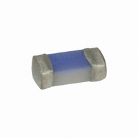
Chip
0603FA Series, Fast-Acting
D D e e s s c c r r i i p p t t i i o o n n
• Fast-acting 0603 surface mount fuse
• Excellent temperature and cycling characteristics
• Compatible with lead free solders and higher
A A g g e e n n c c y y I I n n f f o o r r m m a a t t i i o o n n
• UL Recognition Guide & File numbers:
• CSA Component Acceptance: 053787 C 000 &
E E n n v v i i r r o o n n m m e e n n t t a a l l D D a a t t a a
• Operating temparture: -55ºC to 125ºC with proper
• Load humidity test: MIL-STD-202, Method 103B
• Moisture resistance test: MIL-STD-202, Method 106E
• Thermal shock test: MIL-STD-202, Method 107D
• High frequency vibration test: MIL-STD-202,
O O r r d d e e r r i i n n g g
• Specify packaging and product code
* DC Interrupting rating (Measured at designated voltage, time constant of less than 50 microseconds, battery source)
** DC Cold resistance (Measured at ≤10% of rated current)
*** Typical melting I
† Typical voltage drop (Measured at rated current after temperature stabilizes)
‡ Alpha code to be marked on the top of fuse body for all ratings
0210
P P a a r r t t N N u u m m b b e e r r
0 0 6 6 0 0 3 3 F F A A 2 2 5 5 0 0 - - R R
0 0 6 6 0 0 3 3 F F A A 3 3 7 7 5 5 - - R R
0 0 6 6 0 0 3 3 F F A A 5 5 0 0 0 0 - - R R
0 0 6 6 0 0 3 3 F F A A 7 7 5 5 0 0 - - R R
0 0 6 6 0 0 3 3 F F A A 1 1 - - R R
0 0 6 6 0 0 3 3 F F A A 1 1 . . 2 2 5 5 - - R R
0 0 6 6 0 0 3 3 F F A A 1 1 . . 5 5 - - R R
0 0 6 6 0 0 3 3 F F A A 2 2 - - R R
0 0 6 6 0 0 3 3 F F A A 2 2 . . 5 5 - - R R
0 0 6 6 0 0 3 3 F F A A 3 3 - - R R
0 0 6 6 0 0 3 3 F F A A 3 3 . . 5 5 - - R R
0 0 6 6 0 0 3 3 F F A A 4 4 - - R R
0 0 6 6 0 0 3 3 F F A A 5 5 - - R R
temperature profiles
derating
Method 204D
(i.e., TR/0603FA250-R)
JDYX2 &E19180
Class Number: 1422 30
microseconds) (0603FA4A and 5A measured at interrupting rating)
% % o o f f A A m m p p R R a a t t i i n n g g
BU-SB10140
™
100%
200%
Fuses
2
t (Measured with a battery bank at rated DC voltage, 10x-rated current, not to exceed IR, time constant of calibrated circuit less than 50
E E l l e e c c t t r r i i c c a a l l C C h h a a r r a a c c t t e e r r i i s s t t i i c c s s
C C u u r r r r e e n n t t
( ( a a m m p p s s ) )
R R a a t t i i n n g g
250mA
375mA
500mA
750mA
1.25
1.5
2.5
3.5
1
2
3
4
5
60 Seconds Maximum
32Vac/50dc
32Vac/dc
32Vac/dc
32Vac/dc
32Vac/dc
32Vac/dc
32Vac/dc
32Vac/dc
32Vac/dc
32Vac/dc
32Vac/dc
V V o o l l t t a a g g e e
4 Hours Minimum
R R a a t t i i n n g g
50Vdc
50Vdc
O O p p e e n n i i n n g g T T i i m m e e
R R a a t t i i n n g g ( ( a a m m p p s s ) ) a a t t
R R a a t t e e d d V V o o l l t t a a g g e e * *
I I n n t t e e r r r r u u p p t t i i n n g g
50ac/35dc
50
50
50
50
35
35
35
35
35
35
35
35
S S p p e e c c i i f f i i c c a a t t i i o o n n s s
D D i i m m e e n n s s i i o o n n s s – – m m m m / / i i n n c c h h e e s s
Drawing Not to Scale
R R e e c c o o m m m m e e n n d d e e d d P P a a d d L L a a y y o o u u t t – – m m m m / / i i n n c c h h e e s s
S S o o l l d d e e r r i i n n g g M M e e t t h h o o d d
• Wave solder: 260°C, 10 sec max.
• Solder reflow: 260°C, 30 sec max.
R R e e s s i i s s t t a a n n c c e e * * * * ( ( Ω Ω ) )
Page 1 of 2
D D C C C C o o l l d d
T T y y p p i i c c a a l l
3.100
1.250
1.025
0.450
0.150
0.108
0.086
0.051
0.037
0.028
0.022
0.017
0.011
S S u u r r f f a a c c e e M M o o u u n n t t D D e e v v i i c c e e
HF
FREE
HALOGEN
(0.05)
1.25
Data Sheet 4336
(0.02)
0.00193
M M e e l l t t i i n n g g
T T y y p p i i c c a a l l
0.50
0.0004
0.0009
0.0090
0.0025
0.0130
0.0319
0.0491
0.0625
0.0699
0.1200
0.2430
0.6950
I I
2 2
t t * * * * * *
(0.035)
0.90
V V o o l l t t a a g g e e
T T y y p p i i c c a a l l
D D r r o o p p † †
0.921
0.605
0.600
0.440
0.211
0.151
0.138
0.116
0.113
0.110
0.103
0.097
0.090
Pb
M M a a r r k k i i n n g g ‡ ‡
A A l l p p h h a a
C C o o d d e e
G
O
D
E
F
H
K
N
P
R
S
J
T