852-10-100-30-001000 Mill-Max Manufacturing Corp., 852-10-100-30-001000 Datasheet
852-10-100-30-001000
Manufacturer Part Number
852-10-100-30-001000
Description
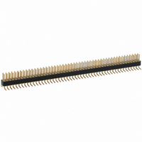
CONN HEADER .132 100POS .050 SMT
Manufacturer
Mill-Max Manufacturing Corp.
Series
852r
Specifications of 852-10-100-30-001000
Number Of Rows
2
Pitch
0.050" (1.27mm)
Contact Type
Male Pin
Connector Type
Header, Unshrouded
Number Of Positions
100
Number Of Positions Loaded
All
Row Spacing
0.050" (1.27mm)
Contact Mating Length
0.118" (3.00mm)
Mounting Type
Surface Mount
Termination
Solder
Contact Finish
Gold
Contact Finish Thickness
10µin (0.25µm)
Color
Black
Product
DIP / SIP Sockets
Number Of Positions / Contacts
100
Contact Plating
Gold
Mounting Style
Through Hole
Termination Style
Solder Pin
Lead Free Status / RoHS Status
Lead free / RoHS Compliant
Features
-
Fastening Type
-
Lead Free Status / Rohs Status
Lead free / RoHS Compliant
Other names
8521010030001000
ED10100
ED10100
w w w. m i l l - m a x . c o m
3,05
3,05
3,05
3,05
0,41 DIA.
0,41 DIA.
Coplanarity 0,13. For Pin Counts
> 40 Consult Tech Support
Coplanarity 0,13. For Pin Counts
> 20 Consult Tech Support
Coplanarity 0,13. For Pin Counts
> 20 Consult Tech Support
Coplanarity 0,13. For Pin Counts
> 40 Consult Tech Support
select
For RoHS compliance
1,27
1,27
5,89
5,89
3,05
3,05
2,21
2,21
4,62
4,62
2,21
2,21
3,02
3,02
3,05
3,05
4,29
4,29
plating code.
1,27
1,27
1,91
1,91
1,91
1,91
3,35
3,35
3,0
3,0
5,26
5,26
3,35
3,35
3,0
3,0
5,26
5,26
X 1,27/2) + 0,38
X 1,27/2) + 0,38
(Number of Pins
(Number of Pins
X 1,27/2) + 0,38
X 1,27/2) + 0,38
(Number of Pins
(Number of Pins
X 1,27) + 0,38
X 1,27) + 0,38
(Number of Pins
(Number of Pins
X 1,27) + 0,38
X 1,27) + 0,38
(Number of Pins
(Number of Pins
1,27
1,27
1,27
1,27
Fig. 1
Fig. 2
Fig. 3
Fig. 4
1,27
1,27
1,27
1,27
1,27 Grid Surface Mount Headers and Sockets
Left Hand
Footprint
3,78
3,78
3,78
3,78
2,21
2,21
Mechanical & Enviromental
1,91
1,91
0,76
0,76
XX=Plating Code
Left Hand
2,54
2,54
Footprint
Right Hand
Footprint
Data, See pg. 4
See Below
0,76
0,76
For Electrical,
Right Hand
Footprint
2,54
2,54
2,54
2,54
1,78
1,78
6,35
6,35
5,08
5,08
Single and Double Row
4,7
4,7
3,43
3,43
Footprint
2,41
2,41
Footprint
1,52
1,52
INTERCONNECTS
0,76
0,76
0,76
0,76
1,27
1,27
1,27
1,27
SPECIFY PLATING CODE XX=
Sleeve (Pin)
Contact (Clip)
SPECIFY PLATING CODE XX=
• Single row intercon-
• Headers (850 &
• Sockets (851 & 853)
• Coplanarity 0,13 (Single Row max 20 pins; Double
• Insulators are high temp. thermoplastic.
Pin Plating
68
Fig. 1R
Fig. 3R
Fig. 1L
Fig. 3L
techical support .
Fig. 2
Fig. 4
nects having an
even number of pins
are now available
with a left or right
hand footprint.
852) use MM# 4006
pins. See page 175
for details.
use MM# 4890-0
receptacles and
accept pin diameters from 0,38 - 0,53. See page 131
for details.
Row max 40 pins). For higher pin counts contact
Single Row Header, Right Hand Footprint
Single Row Socket, Right Hand Footprint
Double Row Header, Even # of pins
Double Row Socket, Even # of pins
Specify # of pins
Specify even # of pins
Specify # of pins
Specify even # of pins
Single Row Header, Left Hand Footprint
Specify even # of pins
Single Row Socket, Left Hand Footprint
Specify even # of pins
Ordering Information
Non-Standard
Non-Standard
44 Plating
44 Plating
30µ” Au
Odd or Even # of pins
Odd or Even # of pins
10µ” Au
13
Even # of pins
Even # of pins
2002/95/EC
853-XX-_ _ _-30-001000
850-XX-0_ _-30-001000
850-XX-0_ _-30-002000
852-XX-_ _ _-30-001000
851-XX-0_ _-30-001000
851-XX-0_ _-30-002000
RoHS
0,25μm Au 5,08μm Sn/Pb 5,08μm Sn
5,08µm Sn/Pb 5,08µmSn/Pb 5,08µm Sn 5,08µm Sn
0,76µm Au
1 0
93
5 1 6 - 9 2 2 - 6 0 0 0
5,08µmSn/Pb 0,76µm Au 5,08µm Sn
99
Series 850, 851
9 0
43
004-100
004-100
852, 853
02-50
02-50
01-50
01-50
4 0
44
Related parts for 852-10-100-30-001000
Image
Part Number
Description
Manufacturer
Datasheet
Request
R

Part Number:
Description:
CONN STRIP HEADER 2X50 .050
Manufacturer:
Mill-Max Manufacturing Corp.
Datasheet:

Part Number:
Description:
CONN HEADER RT ANG 2X50 .050
Manufacturer:
Mill-Max Manufacturing Corp.
Datasheet:

Part Number:
Description:
STANDARD PIN HEADER
Manufacturer:
Mill-Max Manufacturing Corp.

Part Number:
Description:
HDR 26 POS .075
Manufacturer:
Mill-Max Manufacturing Corp.
Datasheet:
Part Number:
Description:
CONN HEADER 20POS .050 DBL T/H
Manufacturer:
Mill-Max Manufacturing Corp.
Datasheet: