43045-1412 Molex Inc, 43045-1412 Datasheet - Page 2
43045-1412
Manufacturer Part Number
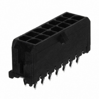
43045-1412
Description
CONN HEADER 14POS 3MM VERT TIN
Manufacturer
Molex Inc
Series
Micro-Fit 3.0™ 43045r
Specifications of 43045-1412
Connector Type
Header, Shrouded
Contact Type
Male Pin
Number Of Positions
14
Number Of Positions Loaded
All
Pitch
0.118" (3.00mm)
Number Of Rows
2
Row Spacing
0.118" (3.00mm)
Mounting Type
Through Hole
Termination
Press-Fit
Fastening Type
Ramp
Features
Board Guide
Contact Finish
Tin
Contact Finish Thickness
100µin (2.54µm)
Color
Black
Contact Termination
Solder
Gender
Plug
No. Of Contacts
14
No. Of Rows
2
Pitch Spacing
3mm
Contact Plating
Tin
Contact Material
Brass
Colour
Black
Product Type
Headers - Shrouded
Number Of Positions / Contacts
14
Mounting Style
Through Hole
Mounting Angle
Vertical
Termination Style
Solder
Housing Material
Thermoplastic, High Temperature
Voltage Rating
250 V
Current Rating
5 A
Connector Mounting
PCB
Rohs Compliant
Yes
Lead Free Status / RoHS Status
Lead free / RoHS Compliant
Contact Mating Length
-
Lead Free Status / Rohs Status
Lead free / RoHS Compliant
Other names
043045-1412
043045-1412-E
0430451412
0430451412-E
43045-1412-E
43045-1412-TR78
430451412
430451412-E
WM4711
043045-1412-E
0430451412
0430451412-E
43045-1412-E
43045-1412-TR78
430451412
430451412-E
WM4711
Available stocks
Company
Part Number
Manufacturer
Quantity
Price
Company:

Part Number:
43045-1412
Manufacturer:
MOLEX
Quantity:
940


REVISION:
DOCUMENT NUMBER:
5.0 PERFORMANCE
5.2 MECHANICAL REQUIREMENTS
H
5.1 ELECTRICAL REQUIREMENTS
(via Current Cycling)
Wire Termination
@ Rated Current
Connector Mate
Retention Force
Unmate Forces
Insertion Force
DESCRIPTION
DESCRIPTION
(into Housing)
Resistance of
Withstanding
Temperature
Capacitance
(in Housing)
(Low Level)
(Low Level)
Resistance
Resistance
Resistance
PS-43045
Insulation
ECR/ECN INFORMATION:
Dielectric
EC No:
Terminal
Terminal
DATE:
Contact
Contact
Contact
Voltage
Rise
and
UCP2003-2248
2003 / 04 / 21
PRODUCT SPECIFICATION
Mate and unmate connector (male to female)
at a rate of 25 ± 6 mm (1 ± ¼ inch) per
minute. (Per circuit)
Axial pullout force on the terminal in the
housing at a rate of 25 ± 6 mm (1 ± ¼ inch)
per minute.
(Does not include wire resistance)
Mate connectors: measure the temperature
rise at the rated current after:
TEST CONDITION
Mate connectors: apply a maximum voltage
of 20 mV and a current of 100 mA.
Mate connectors: apply a maximum voltage
of 20 mV at rated current.
Terminate the applicable wire to the terminal
and measure wire using a voltage of 20 mV
and a current of 100 mA.
Unmate & unmount connectors: apply a
voltage of 500 VDC between adjacent
terminals and between terminals to ground.
Unmate connectors: apply a voltage of {two
times the rated voltage plus 1000 volts} VAC
for 1 minute between adjacent terminals and
between terminals to ground.
Measure between adjacent terminals at 1
MHz.
TEST CONDITION
Apply an axial insertion force on the terminal
at a rate of 25 ± 6 mm (1 ± ¼ inch).
1) 96 hours (steady state)
2) 240 hours (45 minutes ON and 15
3) 96 hours (steady state)
minutes OFF per hour)
TITLE:
CREATED / REVISED BY:
SAMIEC
PRODUCT SPECIFICATION
DUAL ROW CONNECTORS
MICRO-FIT
CHECKED BY:
MUELLER
MINIMUM withdrawal force
MAXIMUM insertion force
MAXIMUM insertion force
MINIMUM retention force
current leakage < 5 mA
TEMPLATE FILENAME: PRODUCT_SPEC[SIZE_A](V.1).DOC
Temperature rise:
+30°C MAXIMUM
REQUIREMENT
REQUIREMENT
1000 Megohms
No breakdown;
24.5 N (5.5 lbf)
14.7 N (3.3 lbf)
8.0 N (1.8 lbf)
3.7 N (0.8 lbf)
10 milliohms
30 milliohms
2 picofarads
5 milliohms
MAXIMUM
MAXIMUM
MAXIMUM
MAXIMUM
MINIMUM
[initial]
[initial]
[initial]
&
APPROVED BY:
MARGULIS
SHEET No.
2
of
5
Related parts for 43045-1412
Image
Part Number
Description
Manufacturer
Datasheet
Request
R

Part Number:
Description:
CONN HEADER 4POS 3MM VERT TIN
Manufacturer:
Molex Inc
Datasheet:

Part Number:
Description:
CONN HEADER 6POS 3MM R/A GOLD
Manufacturer:
Molex Inc
Datasheet:

Part Number:
Description:
CONN HEADER 8POS 3MM VERT TIN
Manufacturer:
Molex Inc
Datasheet:

Part Number:
Description:
CONN HEADER 6POS 3MM VERT GOLD
Manufacturer:
Molex Inc
Datasheet:

Part Number:
Description:
CONN HEADER 12POS 3MM RT ANG TIN
Manufacturer:
Molex Inc
Datasheet:
