3428-6002 3M, 3428-6002 Datasheet - Page 3
3428-6002
Manufacturer Part Number
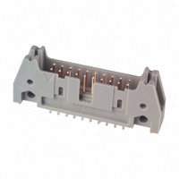
3428-6002
Description
PROTECT HEADER STRT 20 CONTACT
Manufacturer
3M
Series
3000r
Type
PCB Plugr
Datasheets
1.3403-0001.pdf
(32 pages)
2.N3793-6002RB.pdf
(5 pages)
3.N3429-6602RB.pdf
(4 pages)
4.3428-6002.pdf
(5 pages)
Specifications of 3428-6002
Contact Type
Male Pin
Connector Type
Header, Shrouded
Number Of Positions
20
Number Of Positions Loaded
All
Pitch
0.100" (2.54mm)
Number Of Rows
2
Row Spacing
0.100" (2.54mm)
Contact Mating Length
0.240" (6.10mm)
Mounting Type
Through Hole
Termination
Solder
Contact Finish
Gold
Contact Finish Thickness
30µin (0.76µm)
Color
Gray
Product Type
Headers - Latch / Eject
Mounting Style
Through Hole
Mounting Angle
Straight
Termination Style
Solder Pin
Contact Plating
Tin Lead
Agency Approvals
cUL, UL
Angle
Straight
Brand/series
3000 Series
Current, Rating
2 A
Diameter, Hole
2.54 mm
Flammability Rating
UL94V-0
Height
0.68 in.
Length, Ejector/latch
0.100 in. x 0.100 in.
Length, Overall
1.765 "
Length, Pin
0.112 "
Material, Contact
Copper Alloy
Material, Housing
Glass Filled Polyester
Material, Insulation
Glass Filled Polyester (PBT), Glass Filled Polyester (PCT-High Temperature Option)
Mounting Hole Size
0.1 "
Number Of Contacts
20
Pin Spacing
0.1 "
Special Features
Four-Wall
Temperature Rating
-55 to +105 °C
Temperature, Operating
-55 to +105 °C
Lead Free Status / RoHS Status
Contains lead / RoHS non-compliant
Features
-
Fastening Type
-
Lead Free Status / Rohs Status
Lead free / RoHS Compliant
Other names
5400732720
54007327202
80-6100-9708-3
80610097083
MHS20G
MHS20K
54007327202
80-6100-9708-3
80610097083
MHS20G
MHS20K


3M
.100″ × .100″ Latch/Ejector, Straight and Right Angle, High Temp Option
3
Interconnect Solutions
http://www.3M.com/interconnects/
Notes:
“Y”
1. Notches A & C will accomodate 3M Polarizing Keys (3M Part #N3518).
2. Accepts Rear and Front mounting hardware:
3. The recommended PCB hole size for the kinked tail positions on the .112 solder tail connector is .035 ± .002.
Rear Entry: #4-24 thread cutting screw, 3M Part #3341-5, .116 [2.95] dia mounting hole
Front Entry: (Prior to installation of latch on Straight Versions) #2-56 bolt and nut, 3M Part #3341-6,
.106 [2.69] dia mounting hole
Refer to TS-0972 for the positions kinked.
.100 ± .003
[2.54]
Quantity
C L
Number Suffix
[1.52]
.060
Pak 100 4-Wall Header
Pin
Pin
10
14
16
20
24
26
30
34
40
50
60
64
3M Part
3M Part
-5XX2
-6XX2
-5X03
-6X03
-5X05
-6X05
Recommended Mounting Hole Pattern
.300
[7.62]
Side to Side Stackability
3M Part
3M Part
Number
3793
3314
3408
3428
3627
3429
3440
3431
3432
3433
3372
3764
Wire Wrap Tail for up to
3 Levels of Wire Wrap
Thick PC Board
Thick PC Board
Solder Tail for
Solder Tail for
C
Contact Tail
.094 [2.39] to
.062 [1.57]
.125 [3.18]
«.106
[2.69]
Position 1
t t T il
.100 ± .003
[2.54]
(Straight)
3.96 [100.7]
1.26 [32.1]
1.46 [37.2]
1.56 [39.7]
1.76 [44.8]
1.96 [49.8]
2.06 [52.4]
2.26 [57.4]
2.46 [62.6]
2.76 [70.2]
3.26 [82.9]
3.76 [95.6]
(See Note 2)
[8.94]
.352
B
A
or
G Dia
«.116
[2.95]
Di
Dimension E
1.105 [28.07]
1.305 [33.15]
1.405 [35.69]
1.605 [40.77]
1.805 [45.85]
1.905 [48.39]
2.105 [53.47]
2.305 [58.55]
2.605 [66.17]
3.105 [78.87]
3.605 [91.57]
3.805 [96.65]
.61 Ref
[2.84]
[3.94]
[15.5]
.112
.155
B
i
Table 1
Dimensions
E
Table 2
0.0245
0.0245
0.0250
Dimension F
1.065 [27.05]
1.165 [29.59]
1.365 [34.67]
1.565 [39.75]
1.665 [42.29]
1.865 [47.37]
2.065 [52.45]
2.365 [60.07]
2.865 [72.77]
3.365 [85.47]
3.565 [90.55]
.865 [21.97]
[0.622]
[0.622]
[0.635]
”Y”
.100 ± .003
[2.54]
±
±
C
±
.0005
.0005
.002
[0.74]
.029
C L
Pin Cross Section
Recommended Mounting Hole Pattern
0.028
0.028
0.035
Diagonals
1.71 43.43]
1.01 [25.6]
1.21 [30.7]
1.41 [35.8]
1.51 [38.3]
1.91 [48.5]
2.21 [56.1]
2.71 [68.8]
3.21 [81.5]
3.41 [86.6]
.41
[10.4]
Max to Edge of PCB
for Daisy Chain
For technical, sales or ordering information call
.71 [18.0]
.91 [23.1]
[0.71]
[0.71]
[0.90]
±
±
±
D
.001
.001
.003
«.106
.100 ± .003
[2.54]
(Right Angle)
[2.69]
3M is a trademark of 3M Company.
Corner Radii
Notches Provided
0.0075 Ref
0.0075 Ref
0.003 Max
(See Note 2)
[0.191]
[0.191]
Position 1
Polarization
Polarization
[0.08]
[5.89]
.232
A B C
A B C
A B C
A B C
A B C
A B C
A B C
A B C
A B C
A B C
or
B C
B C
C
G Dia
Inch
«.116
Tolerance Unless Noted
[2.95]
[ ] Dimensions for
[0.89] (See Note 3)
Reference only
± .1
.0
Di
Dimension G
.035
3000 Series
.035
.045
Inch
[mm]
[0.89]
[1.14]
800-225-5373
±
± .01
.00
±
±
TS-0772-03
Sheet 3 of 4
.003
i
.003
.003
G
± .005
.000
Related parts for 3428-6002
Image
Part Number
Description
Manufacturer
Datasheet
Request
R

Part Number:
Description:
PROTECT HEADER RT/ANG 20 CONTACT
Manufacturer:
3M
Datasheet:

Part Number:
Description:
CONN HEADER STKD 20POS R/A LO
Manufacturer:
3M
Datasheet:

Part Number:
Description:
CONN HEADER 20POS STR NO LATCH
Manufacturer:
3M
Datasheet:
Part Number:
Description:
CONN HEADER 20POS R/A NO LATCh
Manufacturer:
3M
Datasheet:
Part Number:
Description:
CONN HEADER 20POS R/A NO LATCH
Manufacturer:
3M
Datasheet:

Part Number:
Description:
LAMP INCAND 5MM MIDGET SCREW 6V
Manufacturer:
JKL Components Corp.
Datasheet:

Part Number:
Description:
LAMP, INCAND, SCREW, 6V, 240mW
Manufacturer:
SPC TECHNOLOGY
Datasheet:
Part Number:
Description:
3M-MINI-CLAMP/PLUG/WMIC/2MM/3POS/TYPE A/ORANGE/3M LOGO
Manufacturer:
3M
Datasheet:
Part Number:
Description:
3M-MINI-CLAMP/PLUG/WMIC/2MM/4POS/TYPE A/YELLOW/3M LOGO
Manufacturer:
3M
Datasheet:
Part Number:
Description:
3M-MINI-CLAMP/PLUG/WMIC/2MM/4POS/TYPE A/ORANGE/3M LOGO
Manufacturer:
3M
Datasheet:
Part Number:
Description:
3M-MINI-CLAMP/SKT PANELMOUNT/WMIC/2MM/3POS/TYPE A/RED/3M LOGO
Manufacturer:
3M
Datasheet:
Part Number:
Description:
3M-MINI-CLAMP/SKT PANELMOUNT/WMIC/2MM/3POS/TYPE A/YELLOW/3M LO
Manufacturer:
3M
Datasheet:
Part Number:
Description:
3M-MINI-CLAMP/SKT/WMIC/2MM/3POS/TYPE A/ORANGE/3M LOGO
Manufacturer:
3M
Datasheet:
Part Number:
Description:
3M-MINI-CLAMP/SKT PANELMOUNT/WMIC/2MM/3POS/TYPE A/ORANGE/3M LO
Manufacturer:
3M
Datasheet:
Part Number:
Description:
3M-MINI-CLAMP/SKT PANELMOUNT/WMIC/2MM/4POS/TYPE A/RED/3M LOGO
Manufacturer:
3M
Datasheet: