2510-6002UB 3M, 2510-6002UB Datasheet - Page 4
2510-6002UB
Manufacturer Part Number
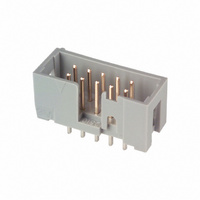
2510-6002UB
Description
SHROUDED HEADER 10 POS STRAIGHT
Manufacturer
3M
Series
2500r
Type
PCB Plugr
Specifications of 2510-6002UB
Contact Type
Male Pin
Connector Type
Header, Shrouded
Number Of Positions
10
Number Of Positions Loaded
All
Pitch
0.100" (2.54mm)
Number Of Rows
2
Row Spacing
0.100" (2.54mm)
Contact Mating Length
0.243" (6.17mm)
Mounting Type
Through Hole
Termination
Solder
Contact Finish
Gold
Contact Finish Thickness
30µin (0.76µm)
Color
Gray
Product Type
Headers - Shrouded
Mounting Style
Through Hole
Mounting Angle
Straight
Termination Style
Solder Pin
Contact Plating
Tin Lead over Nickel
Agency Approvals
cUL, UL
Angle
Straight
Brand/series
2500 Series
Current, Rating
2 A
Flammability Rating
UL94V-0
Length, Overall
0.788 "
Length, Pin
0.243 "
Material, Contact
Copper Alloy
Material, Housing
Glass Filled Polyester
Number Of Contacts
10
Pin Spacing
0.1 "
Special Features
Breakaway, Four-Wall
Strain Relief
Low Profile
Temperature, Operating
-55 to +105 °C
Lead Free Status / RoHS Status
Contains lead / RoHS non-compliant
Features
-
Fastening Type
-
Lead Free Status / Rohs Status
Lead free / RoHS Compliant
Other names
5400782713
54007827139
80-6105-6503-0
80610565030
MHB10G
MHB10K
54007827139
80-6105-6503-0
80610565030
MHB10G
MHB10K


3M
.100”
3
Electronic Solutions Division
Interconnect Solutions
http://www.3M.com/interconnects/
Ordering Information
Prefix:
Blank = Std. Temp. Gray (PBT)(UB or UG Pltg. Req’d)
N = High Temp. Beige (PCT)(UB or UG Pltg. Req’d)
N = High Temp. Black (PCT)(RB Pltg. Req’d)
Notes:
.390
9.91
.100
REF.
2.54
.228
5.79
ORIENTATION TRIANGLE
1. Notches A & C will accomodate 3M Polarizing Keys (3M Part #3518 or N3518).
2. Contact tails .0245 [0.622] wire with .0075 [0.191] corner radii & .028 [.072] diagonal.
3. See page 4 for kink tail positions.
4. Solder stand offs facilitate .01 clearance above board for reflow soldering.
POSITION 1
PIN 1
x
™
.100” Low Profile, Straight Through‑Hole
.194
4.93
Four‑Wall Header
.100
REF.
2.54
NOTCH D
.165
4.19
A
NOTCH A
SEE TABLE 1 & NOTE 1
A
A
B
NOTCH B
NOTCH C
SEE TABLE 1 & NOTE 1
SEE TABLE 1
Pin Quantity:
(See Table 1)
NOTCH E
X25XX-60XX-XX
Solder Tail
02 = for .062 [1.57] thick board
03 = for .094 to .125 [2.39 to 3.18]
K2 = for .062 [1.57] thick board
thick board
.298
7.57
.250
6.35
.338
8.59
Pin Qty
.25
6.43
10
14
16
20
24
26
30
34
40
50
60
64
SECTION A-A
.155 +/- .01[3.94] for 03 versions
.112 +/- .01[2.84] for 02&K2 versions
.788
.988
1.088
1.288
1.488
1.588
1.788
1.988
2.288
2.788
3.288
3.488
.0245
0.62
Plating:
UG = 15µ” [0.38µm] Gold with 200µ” [5.08µm] 60:40
Tin-Lead Solder Tails (RIA E3 & C2 apply)
UB = 30µ” [0.76µm] Gold with 200µ” [5.05µm] 60:40
Tin-Lead Solder Tails (RIA E3 & C2 apply)
RB = 30µ” [0.76µm] Gold with 200µ” [5.08µm]
Matte Tin Solder Tails (RIA E1 & C1 apply)
TYP
For technical, sales or ordering information call
A
0.013
(20.02)
(25.10)
(27.64)
(32.72)
(37.80)
(40.34)
(45.42)
(50.50)
(58.12)
(70.82)
(83.52)
(88.60)
.0005
.243
6.17
Dimensions
Table 1
3M is a trademark of 3M Company.
.708
.908
1.008
1.208
1.408
1.508
1.708
1.908
2.208
2.708
3.208
3.408
Inch
Tolerance Unless Noted
B
(17.98)
(22.06)
(25.60)
(30.68)
(35.76)
(38.30)
(43.38)
(48.46)
(56.08)
(68.78)
(81.48)
(86.56)
[ ] Dimensions for
Reference only
± .1
C
.0
(mm)
Inch
± .01
.00
2500 Series
Polarizing
Notches
ABCDE
ABCDE
ABCDE
ABCDE
ABCDE
ABCDE
ABCDE
ABCDE
ABCDE
ABCDE
800-225-5373
BCDE
± .005
BC
.000
Sheet 2 of 5
TS-0770-E
Related parts for 2510-6002UB
Image
Part Number
Description
Manufacturer
Datasheet
Request
R

Part Number:
Description:
TERM SOLDER SLOT .136" .062"L
Manufacturer:
Mill-Max Manufacturing Corp.
Datasheet:
Part Number:
Description:
TERM SOLDER SLOT .136" .062"L
Manufacturer:
Mill-Max Manufacturing Corp.
Datasheet:
Part Number:
Description:
TERM SOLDER SLOT .136" .062"L
Manufacturer:
Mill-Max Manufacturing Corp.
Datasheet:
Part Number:
Description:
TERM SOLDER SLOT .136" .094"L
Manufacturer:
Mill-Max Manufacturing Corp.
Datasheet:
Part Number:
Description:
TERM SOLDER SLOT .136" .094"L
Manufacturer:
Mill-Max Manufacturing Corp.
Datasheet:

Part Number:
Description:
3M-MINI-CLAMP/PLUG/WMIC/2MM/3POS/TYPE A/ORANGE/3M LOGO
Manufacturer:
3M
Datasheet:
Part Number:
Description:
3M-MINI-CLAMP/PLUG/WMIC/2MM/4POS/TYPE A/YELLOW/3M LOGO
Manufacturer:
3M
Datasheet:
Part Number:
Description:
3M-MINI-CLAMP/PLUG/WMIC/2MM/4POS/TYPE A/ORANGE/3M LOGO
Manufacturer:
3M
Datasheet:
Part Number:
Description:
3M-MINI-CLAMP/SKT PANELMOUNT/WMIC/2MM/3POS/TYPE A/RED/3M LOGO
Manufacturer:
3M
Datasheet:
Part Number:
Description:
3M-MINI-CLAMP/SKT PANELMOUNT/WMIC/2MM/3POS/TYPE A/YELLOW/3M LO
Manufacturer:
3M
Datasheet:
Part Number:
Description:
3M-MINI-CLAMP/SKT/WMIC/2MM/3POS/TYPE A/ORANGE/3M LOGO
Manufacturer:
3M
Datasheet:
Part Number:
Description:
3M-MINI-CLAMP/SKT PANELMOUNT/WMIC/2MM/3POS/TYPE A/ORANGE/3M LO
Manufacturer:
3M
Datasheet:
Part Number:
Description:
3M-MINI-CLAMP/SKT PANELMOUNT/WMIC/2MM/4POS/TYPE A/RED/3M LOGO
Manufacturer:
3M
Datasheet:
Part Number:
Description:
3M-MINI-CLAMP/SKT/WMIC/2MM/4POS/TYPE A/YELLOW/3M LOGO
Manufacturer:
3M
Datasheet:
Part Number:
Description:
3M-MINI-CLAMP/SKT PANELMOUNT/WMIC/2MM/4POS/TYPE A/YELLOW/3M LO
Manufacturer:
3M
Datasheet: