N2510-6V0C-RB-WD 3M, N2510-6V0C-RB-WD Datasheet - Page 2
N2510-6V0C-RB-WD
Manufacturer Part Number
N2510-6V0C-RB-WD
Description
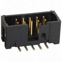
CONN HEADER 10POS SMT VERT 30AU
Manufacturer
3M
Series
2500r
Type
PCB Plugr
Specifications of N2510-6V0C-RB-WD
Contact Type
Male Pin
Connector Type
Header, Shrouded
Number Of Positions
10
Number Of Positions Loaded
All
Pitch
0.100" (2.54mm)
Number Of Rows
2
Row Spacing
0.100" (2.54mm)
Contact Mating Length
0.243" (6.17mm)
Mounting Type
Surface Mount
Termination
Solder
Contact Finish
Gold
Contact Finish Thickness
30µin (0.76µm)
Color
Black
Agency Approvals
cUL, UL
Angle
Straight
Brand/series
2500 Series
Contact Plating
Gold
Current, Rating
2 A
Flammability Rating
UL94V-0
Length, Overall
0.788 "
Length, Pin
0.112 "
Material, Contact
Copper Alloy
Material, Housing
Glass Filled Polyester
Number Of Contacts
10
Pin Spacing
0.1 "
Primary Type
High Temperature
Special Features
Four-Wall
Strain Relief
Low Profile
Temperature, Operating
-55 to +105 °C
Product Type
Headers - Shrouded
Mounting Style
SMD/SMT
Termination Style
Solder
Lead Free Status / RoHS Status
Lead free / RoHS Compliant
Features
-
Fastening Type
-
Lead Free Status / Rohs Status
RoHS Compliant part
Other names
5111174272
51111742723
800009103550
80000913550
MSH10KTR
N25106V0CRBWD
51111742723
800009103550
80000913550
MSH10KTR
N25106V0CRBWD


.100”
3
Electronic Solutions Division
Interconnect Solutions
http://www.3Mconnector.com
Ordering Information
Notes:
Prefix:
N = High Temp. Black (PCT)
Blank = Std. Temp. Gray (PBT)
.390
9.91
.100
REF.
2.54
.228
5.79
ORIENTATION TRIANGLE
1. Notches A & C will accomodate 3M Polarizing Keys (3M Part #3518 or N3518).
2. Contact tails .0245 [0.622] wire with .0075 [0.191] corner radii & .028 [.072] diagonal.
3. See page 4 for kink tail positions.
4. Solder stand offs facilitate .01 clearance above board for reflow soldering.
POSITION 1
(RB, UB, or UG Pltg. Req’d)
PIN 1
x
™
(UB or UG Pltg. Req’d)
.100” Low Profile, Straight Through‑Hole
.194
4.93
.100
REF.
2.54
NOTCH D
.165
4.19
A
NOTCH A
SEE TABLE 1 & NOTE 1
A
A
B
NOTCH B
NOTCH C
SEE TABLE 1 & NOTE 1
SEE TABLE 1
Pin Quantity:
(See Table 1)
NOTCH E
X25XX-60XX-XX
Solder Tail
02 = for .062 [1.57] thick board (Standard)
03 = for .094 to .125 [2.39 to 3.18] thick board
K2 = for .062 [1.57] thick board
.298
7.57
.250
6.35
.338
8.59
Pin Qty
10
14
16
20
24
26
30
34
40
50
60
64
8
.25
6.43
SECTION A-A
0.688
0.788
0.988
1.088
1.288
1.488
1.588
1.788
1.988
2.288
2.788
3.288
3.488
Plating:
RB = 30µ” [0.76µm] Gold with 200µ” [5.08µm]
Matte Tin Solder Tails (RIA E1 & C1 apply)
UG = 15µ” [0.38µm] Gold with 200µ” [5.08µm] 60:40
Tin-Lead Solder Tails (RIA E3 & C2 apply)
UB = 30µ” [0.76µm] Gold with 200µ” [5.05µm] 60:40
Tin-Lead Solder Tails (RIA E3 & C2 apply)
.155 +/- .01[3.94] for 03 versions
.112 +/- .01[2.84] for 02&K2 versions
For technical, sales or ordering information call
.0245
0.62
A
(17.48)
(20.02)
(25.10)
(27.64)
(32.72)
(37.80)
(40.34)
(45.42)
(50.50)
(58.12)
(70.82)
(83.52)
(88.60)
TYP
0.013
.0005
Dimensions
.243
6.17
Table 1
3M is a trademark of 3M Company.
0.608
0.708
0.908
1.008
1.208
1.408
1.508
1.708
1.908
2.208
2.708
3.208
3.408
Inch
Tolerance Unless Noted
B
[ ] Dimensions for
(15.44)
(17.98)
(22.06)
(25.60)
(30.68)
(35.76)
(38.30)
(43.38)
(48.46)
(56.08)
(68.78)
(81.48)
(86.56)
Reference only
± .1
C
.0
(mm)
Inch
± .01
.00
2500 Series
Polarizing
800-225-5373
Notches
ABCDE
ABCDE
ABCDE
ABCDE
ABCDE
ABCDE
ABCDE
ABCDE
ABCDE
ABCDE
BCDE
None
± .005
.000
BC
Sheet 2 of 5
TS-0770-H
Related parts for N2510-6V0C-RB-WD
Image
Part Number
Description
Manufacturer
Datasheet
Request
R

Part Number:
Description:
ANTENNA, GPS, 3M CABLE, SMA
Manufacturer:
WI-SYS
Datasheet:
Part Number:
Description:
ANTENNA, GPS, 3M CABLE, SMA
Manufacturer:
WI-SYS
Datasheet:
Part Number:
Description:
ANTENNA, GPS, 3M CABLE, SMA
Manufacturer:
WI-SYS
Datasheet:

Part Number:
Description:
3M MPro Car Charger
Manufacturer:
3M
Datasheet:

Part Number:
Description:
3M MPro Component Video Cable
Manufacturer:
3M
Datasheet:

Part Number:
Description:
3M-MINI-CLAMP/PLUG/WMIC/2MM/3POS/TYPE A/ORANGE/3M LOGO
Manufacturer:
3M
Datasheet:
Part Number:
Description:
3M-MINI-CLAMP/PLUG/WMIC/2MM/4POS/TYPE A/YELLOW/3M LOGO
Manufacturer:
3M
Datasheet:
Part Number:
Description:
3M-MINI-CLAMP/PLUG/WMIC/2MM/4POS/TYPE A/ORANGE/3M LOGO
Manufacturer:
3M
Datasheet:
Part Number:
Description:
3M-MINI-CLAMP/SKT PANELMOUNT/WMIC/2MM/3POS/TYPE A/RED/3M LOGO
Manufacturer:
3M
Datasheet:
Part Number:
Description:
3M-MINI-CLAMP/SKT PANELMOUNT/WMIC/2MM/3POS/TYPE A/YELLOW/3M LO
Manufacturer:
3M
Datasheet:
Part Number:
Description:
3M-MINI-CLAMP/SKT/WMIC/2MM/3POS/TYPE A/ORANGE/3M LOGO
Manufacturer:
3M
Datasheet:
Part Number:
Description:
3M-MINI-CLAMP/SKT PANELMOUNT/WMIC/2MM/3POS/TYPE A/ORANGE/3M LO
Manufacturer:
3M
Datasheet:
Part Number:
Description:
3M-MINI-CLAMP/SKT PANELMOUNT/WMIC/2MM/4POS/TYPE A/RED/3M LOGO
Manufacturer:
3M
Datasheet:
Part Number:
Description:
3M-MINI-CLAMP/SKT/WMIC/2MM/4POS/TYPE A/YELLOW/3M LOGO
Manufacturer:
3M
Datasheet:
Part Number:
Description:
3M-MINI-CLAMP/SKT PANELMOUNT/WMIC/2MM/4POS/TYPE A/YELLOW/3M LO
Manufacturer:
3M
Datasheet: