MS3102E14S-2P Amphenol Industrial Operations, MS3102E14S-2P Datasheet - Page 62
MS3102E14S-2P
Manufacturer Part Number
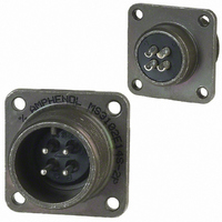
MS3102E14S-2P
Description
CONN RECEPT 4POS BOX MNT W/PINS
Manufacturer
Amphenol Industrial Operations
Series
MIL-5015 Derivativer
Type
Panel Socketr
Specifications of MS3102E14S-2P
Connector Type
Receptacle, Male Pins
Mounting Type
Panel Mount, Flange
Number Of Positions
4
Termination
Solder
Orientation
N (Normal)
Fastening Type
Threaded
Shell Material, Finish
Aluminum, Olive Drab Cadmium Plated
Shell Size - Insert
14S-2
Ingress Protection
Environment Resistant
Connector Body Material
Aluminum Alloy
Gender
Plug
Contact Gender
Pin
Connector Mounting
Box
Connector Shell Size
14S
Insert Arrangement
14S-2
Angle
Straight
Application
True MIL
Brand/series
MS Series
Class
E
Contact Configuration
4#16
Contact Plating
Silver
Contact Type
Pin
Current, Rating
13 A
Diameter, Mounting Hole
0.12 "
Finish, Housing
Olive Drab Cadmium
Housing Type
Metal
Material, Dielectric
Neoprene
Material, Housing
Aluminum Alloy
Mating Type
Threaded
Mount Method
Front
Number Of Contacts
4
Primary Type
5015 MIL Spec
Shell Size
14S
Special Features
Environmental Resistant, Single Key/Keyway Shell Polarization
Voltage, Rating
200/250 VAC/VDC
Wire, Awg
16
Lead Free Status / RoHS Status
Contains lead / RoHS non-compliant
Features
-
Shell Size, Military
-
Lead Free Status / RoHS Status
Contains lead / RoHS non-compliant, Contains lead / RoHS non-compliant
Other names
MS3102E-14S-2P::MS3102E-14S-2P::S10-169214-02P
Available stocks
Company
Part Number
Manufacturer
Quantity
Price
Company:

Part Number:
MS3102E14S-2P
Manufacturer:
ITT
Quantity:
5


Assembly Instructions
for 10-305200 & 10-74900 cable clamps
The 10-305200 cable clamp and MS3420A sleeve illustrated are used only on
the rear of MS-A or C type connectors. The 10-74900 clamp and grommet
assembly can only be used on special feed-thru applications involving dummy
shells, part numbers 10-37090 and 10-113276.
10-305200 Cable Clamp & MS3420A Sleeve
10-74900 Clamp and Grommet Assembly
4
3
3
2
1. Clamping Nut
2. Tapered Sleeve
3. Grommet
1. Clamping Nut
2. Tapered Sleeve
3. Gland
4. Reducing or
2
Telescoping Sleeve
1
1
61
ASSEMBLY
Both clamps are shipped from the factory with lubricant
conforming to MIL-G-3278. Remove any dirt or foreign
material from components with ethyl alcohol and relubri-
cate as outlined under “lubrication.” Place the clamping
nut (1) on the wire bundle or cable with the threads facing
toward the connector or dummy shell. Position the
tapered sleeve (2) on the bundle or cable with the narrow
portion toward the clamping nut (1). Next install either the
gland (3) used with the 10-305200 clamp or thread each
wire through the grommet (3) used with the 10-74900
clamp. Dependent on the application, the wire bundle or
cable is fed through the dummy shell, or the wire ends
are soldered to the connector contacts. Move the compo-
nents forward in the reverse order of preliminary assem-
bly. (In applications where grommets (3) are used, seat
the grommet against the undercut in the back shell
before bringing the tapered sleeve (2) up against it).
Insure proper positioning of glands (3) or grommets (3),
tapered sleeves (2) and clamping nuts (1). Tighten the
clamp using a strap wrench until a metal to metal seat is
obtained.
Related parts for MS3102E14S-2P
Image
Part Number
Description
Manufacturer
Datasheet
Request
R

Part Number:
Description:
CONN RECEPT 10POS W/PIN SOLDER
Manufacturer:
Amphenol Industrial Operations

Part Number:
Description:
CONN RECEPT 19POS W/SOCKT SOLDER
Manufacturer:
Amphenol Industrial Operations

Part Number:
Description:
CONN RECEPT 4POS BOX MNT W/PINS
Manufacturer:
Amphenol Industrial Operations

Part Number:
Description:
CONN RECEPT 19POS BOX MNT W/PINS
Manufacturer:
Amphenol Industrial Operations

Part Number:
Description:
CONN RCPT 7POS BOX MNT W/PINS
Manufacturer:
Amphenol Industrial Operations

Part Number:
Description:
JAM NUT CONN, RCPT, SIZE 9, 6POS, PANEL
Manufacturer:
Amphenol Industrial Operations
Datasheet:
Part Number:
Description:
PT 41C 41#20 PIN RECP
Manufacturer:
Amphenol Industrial Operations
Part Number:
Description:
PT 41C 41#20 SKT RECP
Manufacturer:
Amphenol Industrial Operations