W91-X112-20 Tyco Electronics, W91-X112-20 Datasheet - Page 3
W91-X112-20
Manufacturer Part Number
W91-X112-20
Description
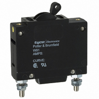
CIRCUIT BREAK SP 20A PNL
Manufacturer
Tyco Electronics
Series
W91r
Specifications of W91-X112-20
Breaker Type
Hydraulic-Magnetic
Voltage
277VAC
Current - Trip (it)
20A
Number Of Poles
1
Actuator Type
Toggle
Mounting Type
Panel Mount
Input Voltage Vac
277V
No. Of Poles
1
Current Rating
20A
Interrupting Capacity
5kA
Dielectric Strength
1.5kV
Trip Time
20s
Voltage Rating Vdc
65V
Trip Time Max
20sec
Product Type
Circuit Breakers
Voltage Rating
277 VoltsAC
Mounting Style
Through Hole
Termination Style
Screw
Circuit Function
Series Trip
Color
Black
Features
Several delay curve options, trip-free operation
Illuminated
No
Product
Hydraulic Magnetic Circuit Breakers
Height
63.5 mm
Length
46.86 mm
Width
19.05 mm
Lead Free Status / RoHS Status
Lead free / RoHS Compliant
Lead Free Status / RoHS Status
Lead free / RoHS Compliant, Lead free / RoHS Compliant
Other names
2-1393254-5
PB434
PB434


Ordering Information
Authorized distributors are more likely to stock the following items.
Ordering Information
Authorized distributors are more likely to stock the following items.
W6 Series
1. Circuit Breaker Mounting:
2. Number of Poles:
3. Circuit Function: (Only X is VDE approved)
4. Actuator: (One actuator per pole)
5. Termination:
6. Maximum Line Voltage: (See Table 1 for current ranges)
7. Time Delay Curve:
8. Amp Rating:
9. VDE Approval:
W9 Series
1. Circuit Breaker Mounting:
2. Number of Poles:
3. Circuit Function: (Only X is VDE approved)
4. Actuator: (One actuator per pole):
5. Maximum Line Voltage: (See Table 1 for current ranges)
6. Time Delay Curve:
7. Amp Rating:
8. VDE Approval:
W91-X112-1
W91-X112-2
W91-X112-3
W91-X112-5
W91-X112-7
W91-X112-10
W67-A2Q12-5
W67-A2Q12-10
W67-X2Q10-3
W67-X2Q10-5
W67-X2Q12-2
W67-X2Q12-3
Dimensions are shown for
reference purposes only.
W = #6-32 mounting threads.
M = M3.0 x 0.5 mounting threads.
67 = Single pole
A = Series trip with auxiliary switch (.093” QC)
1 = Black toggle
2 = White toggle
Q = .250” QC (DIN 46 244) [25A Max. VDE]
Note: “T” termination must be used for all ratings of 31 amps or above.
UL/CSA
TYPES
0 = Instantaneous
2 = Standard delay
3 = Short delay
53 = DC high inrush
0.20
0.25
Blank = UL/CSA approved breaker
V = VDE approved breaker without auxiliary switch
W = #6-32 mounting threads.
91 = Single pole
A = Series trip with auxiliary switch (.093” QC)
1 = Black toggle
UL/CSA
TYPES
0 = Instantaneous
2 = Standard delay
3 = Short delay
53 = DC high inrush
0.20
0.25
0.50
Blank = UL/CSA approved breaker
V = VDE approved breaker without auxiliary switch
0.50
0.75
1 = 277VAC, 50/60 Hz.
2 = 277/480
3 = 250VAC, 400 Hz.
5 = 65VDC
7 = AC/DC 277VAC or 65VDC
1 = 277VAC, 50/60 Hz.
2 = 277/480
3 = 250VAC, 400 Hz.
5 = 65VDC
7 = AC/DC 277VAC or 65VDC
0.75
1.0
1.5
(Delay curve 34 must be specified.)
(Delay curve 34 must be specified.)
W91-X112-15
W91-X112-20
W91-X112-40
W91-X112-50
W91-X113-5
W91-X113-10
W67-X2Q12-5
W67-X2Q12-7
W67-X2Q12-10
W67-X2Q12-15
W67-X2Q12-20
W67-X2Q12-30
1.0
1.5
3 = Black rocker
4 = White rocker
92 = Two pole
2.0
2.5
3.0
68 = Two pole
2.0
2.5
2 = White toggle
10 = AC high inrush (Motor start)
12 = AC high inrush version of #2
13 = AC high inrush version of #3
34 = Combination AC/DC standard delay
10 = AC high inrush (Motor start)
12 = AC high inrush version of #2
13 = AC high inrush version of #3
34 = Combination AC/DC standard delay
M = M3.0 x 0.5 mounting threads.
3.0
3.5
3.5
4.0
5.0
W91-X113-15
W91-X150-5
W91-X152-10
W91-X152-15
W91-X152-20
W91-X152-30
5 = Red rocker
6 = Grey rocker
W67-X2Q13-1
W67-X2Q13-2
W67-X2Q13-3
W67-X2Q13-10
W67-X2Q13-15
W67-X2Q13-20
Dimensions are in inches over
(millimeters) unless otherwise
specified.
93 = Three pole
4.0
5.0
VDE
TYPES
6.0
7 .0
7 .5
VDE
TYPES
69 = Three pole
X = Series trip
S = #8-32 screw [30A Max. VDE]
X = Series trip
6.0
7 .0
1 = 250VAC, 415/240VAC
5 = 65VDC
7 = AC/DC 250VAC, 415/240VAC, 65VDC
1 = 250VAC, 415/240VAC
5 = 65VDC
7 = AC/DC 250VAC, 415/240VAC, 65VDC
W91-X152-40
W91-X152-50
W91-X1110-20
W92-X112-1
W92-X112-2
W92-X112-3
Typical Part No.
W67-X2Q13-25
W67-X2Q13-30
W67-X2Q50-5
W67-X2Q50-10
W67-X2Q52-5
W67-X2Q52-10
9 = Red toggle
(Delay curve 34 must be specified.)
10.0
8.0
9.0
(Delay curve 34 must be specified.
7 .5
8.0
Typical Part No.
94 = Four pole
Catalog 1308242
Notes: Curves may be specified with increased pulse tolerance for 1/2 cycle
11.0
12.0
15.0
Issued 3-03
9.0
10.0
70 = Four pole
Notes: Curves may be specified with increased pulse tolerance for 1/2 cycle by
adding "P" after curve, See delay curve section for availability and details
by adding "P" after curve. See delay curve section for availability and details.
W92-X112-5
W92-X112-7
W92-X112-10
W92-X112-15
W92-X112-20
W92-X112-25
W67-X2Q52-15
W67-X2Q52-20
W67-X2Q52-30
W67-X2Q110-15
W67-X2Q110-20
W68-X2Q12-3
B
Specifications and availability
subject to change.
11.0
12.0
20.0
25.0
30.0
W 67- X
T = #10-32 screw [50A Max. VDE]
B
15.0
20.0
)
W
35.0
40.0
45.0
W92-X112-30
W92-X112-40
W92-X112-50
W92-X113-15
W92-X113-20
W92-X1110-20
W68-X2Q12-5
W68-X2Q12-7
W68-X2Q12-10
W68-X2Q12-15
W68-X2Q12-20
W68-X2Q12-25
25.0
30.0
91- X
50.0
Consult factory for other values
35.0
40.0
2
Q
45.0
50.0
1
W92-X1110-30
W93-X112-5
W93-X112-10
W93-X112-15
W93-X112-20
W93-X112-25
W68-X2Q12-30
W68-X2Q13-15
W68-X2Q110-10
W68-X2Q110-20
W69-X2Q12-5
W69-X2Q12-10
1
Consult factory for
other values.
1
.
2-
2- 20
www.tycoelectronics.com
Technical support:
Refer to inside back cover.
W93-X112-30
W93-X112-40
W93-X112-50
W93-X1110-20
W93-X1110-30
W69-X2Q12-15
W69-X2Q12-20
W69-X2Q12-25
W69-X2Q12-30
W69-X2Q110-20
W69-X2Q110-30
20
P&B
121
Related parts for W91-X112-20
Image
Part Number
Description
Manufacturer
Datasheet
Request
R

Part Number:
Description:
W91-A112-15=M6/M7/M9/W6/W7
Manufacturer:
Tyco Electronics
Datasheet:
Part Number:
Description:
W91-X1040-15=M6/M7/M9/W6/W7
Manufacturer:
Tyco Electronics
Datasheet:
Part Number:
Description:
W91-X1040-50=M6/M7/M9/W6/W7
Manufacturer:
Tyco Electronics
Datasheet:
Part Number:
Description:
W91-X152-35=M6/M7/M9/W6/W7
Manufacturer:
Tyco Electronics
Datasheet:

Part Number:
Description:
CIRCUIT BREAK SP 10A PNL
Manufacturer:
Tyco Electronics
Datasheet:
Part Number:
Description:
CIRCUIT BREAKER SWITCH 15A BLK
Manufacturer:
Tyco Electronics
Datasheet:
Part Number:
Description:
CIRCUIT BREAKER SWITCH 40A BLK
Manufacturer:
Tyco Electronics
Datasheet:
Part Number:
Description:
CIRCUIT BREAKER SWITCH 50A BLK
Manufacturer:
Tyco Electronics
Datasheet:
Part Number:
Description:
CIRCUIT BREAKER SWITCH 5A BLACK
Manufacturer:
Tyco Electronics
Datasheet:
Part Number:
Description:
CIRCUIT BREAKER SWITCH 30A BLK
Manufacturer:
Tyco Electronics
Datasheet:
Part Number:
Description:
CIRCUIT BREAKER SWITCH 10A BLK
Manufacturer:
Tyco Electronics
Datasheet:
Part Number:
Description:
CIRCUIT BREAKER SWITCH 10A BLK
Manufacturer:
Tyco Electronics
Datasheet:
Part Number:
Description:
CIRCUIT BREAKER SWITCH 7A BLACK
Manufacturer:
Tyco Electronics
Datasheet:
Part Number:
Description:
CIRCUIT BREAKER SWITCH 50A BLK
Manufacturer:
Tyco Electronics
Datasheet:
