CV35A090 Tusonix, CV35A090 Datasheet - Page 6
CV35A090
Manufacturer Part Number
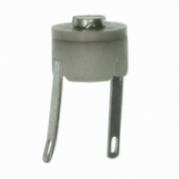
CV35A090
Description
TRIMMER CAP 2.5 TO 9.0PF
Manufacturer
Tusonix
Series
518r
Specifications of CV35A090
Capacitance Range
2.5 ~ 9pF
Adjustment Type
Top Adjustment
Voltage - Rated
100V
Size / Dimension
Round - 0.218" Dia (5.54mm)
Height
0.145" (3.68mm)
Mounting Type
Through Hole
Features
General Purpose
Package / Case
5.54mm Round
Lead Free Status / RoHS Status
Contains lead / RoHS non-compliant
Other names
0518-016-A-2.5-9
0518-016A1.0-3
410-1223
518016A2.59
0518-016A1.0-3
410-1223
518016A2.59


The products listed in this catalog are only a few of the thou-
The products listed in this catalog are only a few of the thou-
sands of variations that TUSONIX produces. For custom
sands of variations that TUSONIX produces. For custom
applications please contact the factory direct.
applications please contact the factory direct.
The products listed in this catalog are only a few of the thou-
The products listed in this catalog are only a few of the thou-
The products listed in this catalog are only a few of the thou-
sands of variations that TUSONIX produces. For custom
sands of variations that TUSONIX produces. For custom
sands of variations that TUSONIX produces. For custom
applications please contact the factory direct.
applications please contact the factory direct.
applications please contact the factory direct.
CAP
CAP
temperature (25°C ± 5°C) and at a frequency
“Q” F
“Q” F
perature (25°C ± 5°C) and at a frequency of
approximately 1 Megahertz, the capacitor at
approximately maximum rated capacitance
setting shall have a “Q” Value not less than
INSULA
INSULA
proximately maximum capacitance setting
shall be 10 gigaohms minimum at 25°C ± 5°C
when measured at 100 volts dc. The voltage
shall be applied through a protective series
resistance not exceeding 1 megaohm. The
electrification time shall not exceed 1 minute.
DIELECTRIC STRENGTH:
DIELECTRIC STRENGTH:
DIELECTRIC STRENGTH: The capacitor,
set at approximately maximum capacitance,
shall withstand voltage between terminals for
1 to 5 sec. as indicated for the respective
style. The surge current shall be limited to
50mA maximum.
T T T T T ORQUE:
TEMPERA
TEMPERA
CAP
CAP
CAPACIT
of 0.1 to 1 Megahertz, the minimum capaci-
tance shall not be greater than that specified
at minimum setting with a +10% tolerance
and the maximum capacitance shall not be
less than that specified maximum setting with
a - 10% tolerance.
“Q” F
“Q” F
“Q” FACT
indicated for the respective style.
INSULA
INSULA
INSULATION RESIST
DIELECTRIC STRENGTH:
DIELECTRIC STRENGTH:
torque required to start and maintain rota-
tion of the rotor through one full turn, shall be
as indicated for the respective style.
TEMPERA
TEMPERATURE CHARACTERISTIC:
TEMPERA
T.C. of capacitance shall be within the limits
shown in the table to the right. The T.C. shall
be determined by measuring the capacitance
(capacitor shall be set at approximately 75%
of the guaranteed maximum capacitance) at
+25, -55°C and either +85°C or +125°C,
whichever is applicable to the respective
style, at a frequency of 0.1 to 1 Megahertz.
Each measurement shall be made after the
capacitor has reached thermal stability.
ORQUE:
ORQUE:
TUSONIX on-line: www
TUSONIX on-line: www
TUSONIX on-line: www
TUSONIX on-line: www
TUSONIX on-line: www.tusonix.com
ORQUE:
ORQUE: When measured 25°C ± 5°C, the
T
uct data sheets in Adobe Acrobat
Agents and Distributors. We also offer Stock Check and Cross Reference features for our custom-
ers’ convenience. An on-line request form allows customers to immediately specify product re-
quirements and request information or samples. TUSONIX continually strives to improve and
enhance its web site in accordance with its customers’ needs.
ACIT
ACIT
ACIT
ACITANCE:
ACT
ACT
ACT
ACTOR:
At www
TION RESIST
TION RESIST
TION RESISTANCE:
he TUSONIX Web Site provides visitors with a wide range of product and ordering information.
TION RESIST
ANCE:
ANCE:
ANCE:
ANCE: When measured at room
OR:
OR:
OR: When measured at room tem-
OR:
TURE CHARACTERISTIC:
TURE CHARACTERISTIC:
TURE CHARACTERISTIC:
TURE CHARACTERISTIC: The
www
www
www.tusonix.com
www
.tusonix.com
.tusonix.com
.tusonix.com
.tusonix.com, customers can view product information, download catalogs and prod-
ANCE:
ANCE:
ANCE: The I.R. at ap-
ANCE:
.tusonix.com
.tusonix.com
.tusonix.com
.tusonix.com
CAP
CAP
CAP
CAP
CAPACIT
shall be determined as the greatest difference
between any two of the three 25°C measure-
ments obtained during the temperature char-
acteristic test. The capacitance drift shall not
exceed 0.75% or 0.5pF, whichever is greater.
ACCELERA
ACCELERA
ACCELERA
ACCELERA
ACCELERATED LIFE TEST
at approximately 75% of the guaranteed maxi-
mum capacitance, shall be tested for 250 hours
at twice rated voltage, and at a temperature
equal to the maximum operating temperature
± 3°C for the respective style. At the end of
this period the capacitance shall not have
changed more than ±5% or ±0.5pF, whichever
is greater, from its value before the life test.
The I.R. shall be 1 gigaohm minimum and the
“Q” at 1 MHz shall be a minimum of 40% of
the initial test limit.
TEMPERA
TEMPERA
TEMPERA
TEMPERA
TEMPERATURE CYCLING & HUMIDITY
The capacitor at approximately 75% of the
guaranteed maximum capacitance, shall be
given a treatment consisting of 5 temperature
cycles as follows: Cool the capacitors to -55°C
±3°C. Remove the capacitor from the cooling
chamber and allow to reach room temp.
®
.pdf format, as well as view or link to Sales Offices, International
T T T T T ype Code
ACIT
ACIT
ACIT
ACITANCE DRIFT
Dielectric
Dielectric
Dielectric
Dielectric
Dielectric
ype Code
ype Code
ype Code
ype Code
A A A A A
B B B B B
C C C C C
D D D D D
A A A A A
F F F F F
F F F F F
ANCE DRIFT
ANCE DRIFT
ANCE DRIFT
ANCE DRIFT: : : : : The capacitance drift
TURE CYCLING & HUMIDITY
TURE CYCLING & HUMIDITY
TURE CYCLING & HUMIDITY
TURE CYCLING & HUMIDITY: : : : :
TED LIFE TEST
TED LIFE TEST
TED LIFE TEST
TED LIFE TEST: : : : : The capacitor,
+1.5
+1.5
+1.5
+1.5
+1.5
+3.0
+3.0
+3.0
+3.0
+3.0
-4.5
-4.5
-4.5
-4.5
-4.5
-1.0
-1.0
-1.0
-1.0
-1.0
-1.0
-1.0
-1.0
-1.0
-1.0
-2.1
-2.1
-2.1
-2.1
-2.1
Min.
Min.
Min.
Min.
Min.
0.0
0.0
0.0
0.0
0.0
-55°C
-55°C
-55°C
-55°C
-55°C
T T T T T rimmer Capacitor Specifications
rimmer Capacitor Specifications
rimmer Capacitor Specifications
rimmer Capacitor Specifications
rimmer Capacitor Specifications
Max.
Max.
Max.
Max.
Max.
+14.0
+14.0
+14.0
+14.0
+14.0
+14.0
+14.0
+14.0
+14.0
+14.0
+2.0
+2.0
+2.0
+2.0
+2.0
+3.5
+3.5
+3.5
+3.5
+3.5
+6.5
+6.5
+6.5
+6.5
+6.5
+8.2
+8.2
+8.2
+8.2
+8.2
+4.2
+4.2
+4.2
+4.2
+4.2
P/N 518, 528, 538
P/N 518, 528, 538
P/N 518, 528, 538
P/N 518, 528, 538
P/N 518, 528, 538
Percent Capacitance Change
Percent Capacitance Change
Percent Capacitance Change
Percent Capacitance Change
Percent Capacitance Change
P/N 513
P/N 513
P/N 513
P/N 513
P/N 513
From V
From V
From V
From V
From Value @ 25°C
-10.0
-10.0
-10.0
-10.0
-10.0
-2.5
-2.5
-2.5
-2.5
-4.0
-4.0
-5.0
-5.0
-3.8
-3.8
-8.0
-8.0
-2.5
-2.5
-2.5
-2.5
-2.5
-2.5
-4.0
-4.0
-4.0
-5.0
-5.0
-5.0
-3.8
-3.8
-3.8
-8.0
-8.0
-8.0
Min.
Min.
Min.
Min.
Min.
Then place in an oven at a temperature equal
to maximum operating temperature ±3°C of
the respective style. Remove from oven and
allow capacitor to cool to room temperature.
The capacitor shall be held at the specified
minimum and maximum temperatures long
enough to reach equilibrium and in no case
less than 15 minutes. The rate of change of
temperature in cooling from room tempera-
ture, or heating above it shall not be less than
3°C per minute.
The temperature cycles shall be followed by
exposures for 96 hours to a relative humidity
of 95% at 40°C ±3°C. The capacitor shall
then be removed from the humidity chamber
and held at 25°C ±5°C with a maximum hu-
midity of 50% for four hours. The I.R. shall
be at least 1 gigaohm, the “Q” at 1 MHz is at
least 40% of initial test limit and the capaci-
tance shall not have changed by more than
±3% or ±0.5pF, whichever is greater, from
its value prior to the start of the temperature
cycling.
+85°C
+85°C
+85°C
+85°C
+85°C
alue @ 25°C
alue @ 25°C
alue @ 25°C
alue @ 25°C
Max.
Max.
Max.
Max.
Max.
+2.0
+2.0
+2.0
+2.0
+2.0
+1.1
+1.1
+1.1
+1.1
+1.1
-0.5
-0.5
-0.5
-0.5
-0.5
-1.0
-1.0
-1.0
-1.0
-1.0
-1.5
-1.5
-1.5
-1.5
-1.5
-3.0
-3.0
-3.0
-3.0
-3.0
-3.0
-3.0
-3.0
-3.0
-3.0
-17.0
-17.0
-17.0
-17.0
-17.0
Min.
Min.
Min.
Min.
Min.
-4.2
-4.2
-4.2
-4.2
-4.2
-4.2
-4.2
-4.2
-4.2
-4.2
-6.7
-6.7
-6.7
-6.7
-6.7
-8.5
-8.5
-8.5
-8.5
-8.5
-- -- -- -- --
-- -- -- -- --
+125°C
+125°C
+125°C
+125°C
+125°C
Max.
Max.
Max.
Max.
Max.
+3.4
+3.4
+3.4
+3.4
+3.4
-0.8
-0.8
-0.8
-1.7
-1.7
-1.7
-2.5
-2.5
-2.5
-5.0
-5.0
-5.0
-0.8
-0.8
-1.7
-1.7
-2.5
-2.5
-5.0
-5.0
-- -- -- -- --
-- -- -- -- --
6
Related parts for CV35A090
Image
Part Number
Description
Manufacturer
Datasheet
Request
R

Part Number:
Description:
FILTER EMI 8200 PF PI TYPE
Manufacturer:
Tusonix
Datasheet:

Part Number:
Description:
FILTER EMI 1500 PF PI TYPE
Manufacturer:
Tusonix
Datasheet:

Part Number:
Description:
EMI Filter 10A 100VDC Flat Style SMD
Manufacturer:
Tusonix
Datasheet:

Part Number:
Description:
EMI/RFI Suppressors & Ferrites 5000pF 100Volts
Manufacturer:
Tusonix
Datasheet:


Part Number:
Description:
TRIMMER CAP SMD 8.0 TO 25.0PF
Manufacturer:
Tusonix
Datasheet:

Part Number:
Description:
TRIMMER CAP SMD 9.0 TO 35.0PF
Manufacturer:
Tusonix
Datasheet:

Part Number:
Description:
TRIMMER CAP SMD 2.5 TO 11.0PF
Manufacturer:
Tusonix
Datasheet:

Part Number:
Description:
TRIMMER CAP SMD 2.0 TO 8.0PF
Manufacturer:
Tusonix
Datasheet:

Part Number:
Description:
TRIMMER CAP SMD 15.0 TO 60.0PF
Manufacturer:
Tusonix
Datasheet:
Part Number:
Description:
EMI Filter 10A 100VDC Flat Style SMD
Manufacturer:
Tusonix
Datasheet:
Part Number:
Description:
EMI Filter 10A AXL Thru-Hole
Manufacturer:
Tusonix
Datasheet:
Part Number:
Description:
EMI Filter 10A 140VDC PC Pins Panel Mount/Through Hole
Manufacturer:
Tusonix
Datasheet: