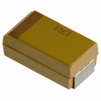
T491B155K025AS Kemet, T491B155K025AS Datasheet - Page 14

T491B155K025AS
Manufacturer Part Number
T491B155K025AS
Description
CAPACITOR TANT 1.5UF 25V 10% SMD
Manufacturer
Kemet
Series
T491r
Type
Moldedr
Datasheet
1.T491B155K025AS.pdf
(100 pages)
Specifications of T491B155K025AS
Capacitance
1.5µF
Voltage - Rated
25V
Tolerance
±10%
Esr (equivalent Series Resistance)
5.000 Ohm
Operating Temperature
-55°C ~ 125°C
Mounting Type
Surface Mount
Package / Case
1210 (3528 Metric)
Size / Dimension
0.138" L x 0.110" W (3.50mm x 2.80mm)
Height
0.075" (1.90mm)
Manufacturer Size Code
B
Features
General Purpose
Lead Free Status / RoHS Status
Contains lead / RoHS non-compliant
Lead Spacing
-
Other names
399-1625-2
12
All conventional reliability testing is conducted
under steady-state DC voltage. Experience indi-
cates that AC ripple, within the limits prescribed,
has little effect on failure rate. Heavy surge cur-
rents are possible in some applications, howev-
er. Circuit impedance may be very low (below the
recommended 0.1 ohm/volt) or there may be dri-
ving inductance to cause voltage “ringing.” Surge
current may appear during turn-on of equipment,
for example. Failure rate under current-surge
conditions may not be predictable from conven-
tional life test data.
Capacitors are capable of withstanding a 4 ±1
second charge of rated voltage (±2%) through a
total circuit resistance (excluding the capacitor) of
1 ±0.2 ohms at +25°C, followed by a 4 ±1 second
discharge to a voltage below 1% of the rated volt-
age. This cycle is repeated consecutively three
(3) times. Post test performance:
100% production surge current testing is per-
formed on all Tantalum Chip series for case sizes
C, D, E, X, U, V. The total test circuit resistance
is
rated voltage for all series except the T495 and
T510 which are surged at 100% of rated voltage.
Four surge cycles are applied. Parts not capable
of surviving this test are removed at subsequent
electrical screening. See T493 Series on page 22
for specific surge options.
Post Test Performance:
Post Test Performance:
Post Test Performance:
a. Capacitance — within ±10% of initial value
b. DC Leakage — within initial limit
c. Dissipation Factor — within initial limit
d. ESR — within initial limit
e. Physical — no degradation of function
a. Capacitance — within ±10% of initial value
b. DC Leakage — within 125% of initial limit
c. Dissipation Factor — within initial limit
d. ESR — within initial limit
e. Physical — no degradation of function
a. Capacitance — within ±10% of initial value
b. DC Leakage — within 125% of initial limit
c. Dissipation Factor — within initial limit
d. ESR — within initial limit
e. Physical — no degradation of function
2,000 hours, +125 C, Unbiased, Mounted
2,000 hours, +85 C, Rated Voltage, Mounted
2,000 hours, +125 C, 2/3 Rated Voltage,
Mounted
a. Capacitance — within ±5% of initial value
b. DC Leakage — within initial limit
c. Dissipation Factor — within initial limit
0.5 ohms. The applied voltage is 75% of
©KEMET Electronics Corporation, P.O. Box 5928, Greenville, S.C. 29606, (864) 963-6300
SOLID TANTALUM CHIP CAPACITORS
Post Test Performance:
Post Test Performance:
Applies to Solder and Tin Coated terminations
only. Does not apply to optional gold-plated ter-
minations.
Post Test Performance:
Post Test Performance:
a. Capacitance — within ±10% of initial value
b. DC Leakage — within initial limit
c. Dissipation Factor -— within initial limit
d. Physical — no degradation of case, termi-
a. Capacitance — within ±10% of Initial Value
b. DC Leakage — within Initial Limit
c. Dissipation Factor — within Initial Limit
a. Capacitance — within ± 10% of initial value
b. DC Leakage — within initial limit
c. Dissipation Factor — within initial limit
a. Capacitance — within ±10% of initial value
b. DC Leakage — within initial limit
c. Dissipation Factor — within initial limit
Mil-Std-202, Method 215
Mil-Std-810, Method 508
UL94 VO Classification
Wave Solder
+260 ±5 C, 10 Seconds
Infrared Reflow
+230 ±5 C, 30 Seconds
Vapor Phase Reflow
+215 ±5 C, 2 minutes
Mil-Std-202, Method 208
ANSI/J-STD-002, Test B
Mil-Std-202, Method 204, Condition D,
10 Hz to 2,000 Hz, 20G Peak
Mil-Std-202, Method 213, Condition I,
100 G Peak
One Pound (454 grams), 30 Seconds
nals or marking.
Encapsulant materials meet this
classification.


