GMF05LC-GS08 Vishay, GMF05LC-GS08 Datasheet - Page 2
GMF05LC-GS08
Manufacturer Part Number
GMF05LC-GS08
Description
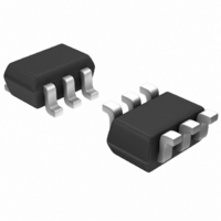
DIODE ARRAY ESD 5.0V SOT363
Manufacturer
Vishay
Datasheet
1.GMF05LC-HS3-GS08.pdf
(7 pages)
Specifications of GMF05LC-GS08
Voltage - Reverse Standoff (typ)
5V
Voltage - Breakdown
6V
Power (watts)
70W
Polarization
4 Channel Array - Bidirectional
Mounting Type
Surface Mount
Package / Case
SC-70-6, SC-88, SOT-363
Lead Free Status / RoHS Status
Lead free / RoHS Compliant
Other names
751-1399-2
GMF05LC-GS08GITR
GMF05LC-GS08GITR
GMF05LC-GS08GITR
GMF05LC-GS08GITR
Available stocks
Company
Part Number
Manufacturer
Quantity
Price

Part Number:
GMF05LC-GS08
Manufacturer:
VISHAY/威世
Quantity:
20 000


GMF05LC-HS3
Vishay Semiconductors
BiAs-Mode (5-line Bidirectional Asymmetrical protection mode)
With the GMF05LC-HS3 up to 5 signal- or data-lines (L1 - L5) can be protected against voltage transients.
With pin 2 connected to ground and pin 1; 3 up tp pin 6 connected to a signal- or data-line which has to be
protected. As long as the voltage level on the data- or signal-line is between 0 V (ground level) and the specified
Maximum Reverse Working Voltage (V
isolation to the ground line. The protection device behaves like an open switch.
As soon as any positive transient voltage signal exceeds the break through voltage level of the protection
diode, the diode becomes conductive and shorts the transient current to ground. Now the protection device
behaves like a closed switch. The Clamping Voltage (V
plus the voltage drop at the series impedance (resistance and inductance) of the protection device.
Any negative transient signal will be clamped accordingly. The negative transient current is flowing in the for-
ward direction of the protection diode. The low Forward Voltage (V
ground level.
Due to the different clamping levels in forward and reverse direction the GMF05LC-HS3 clamping behaviour
is Bidirectional and Asymmetrical (BiAs).
Electrical Characteristics
Ratings at 25 °C ambient temperature, unless otherwise specified
GMF05LC-HS3
BiAs mode: each input (pin 1, 3, 4, 5, 6) to ground (pin 2)
If a higher surge current or Peak Pulse current (I
can also be used in parallel in order to "multiply" the performance.
If two diodes are switched in parallel you get
www.vishay.com
2
Protection paths
Reverse stand-off voltage
Reverse current
Reverse breakdown voltage
Reverse clamping voltage
Forward clamping voltage
Line capacitance
20739
L1
L2
Parameter
•
•
•
•
•
double surge power = double peak pulse current (2 x I
half of the line inductance = reduced clamping voltage
half of the line resistance = reduced clamping voltage
double line Capacitance (2 x C
double Reverse leakage current (2 x I
at I
at I
For technical support, please contact: ESD-Protection@vishay.com
number of line which can be protected
PP
PP
at I
at I
= I
= I
1
2
3
PP
F
at V
Test conditions/remarks
at V
PPM
PPM
= 1 A; acc. IEC 61000-4-5
= 1 A; acc. IEC 61000-4-5
at V
R
R
= 5 A; acc. IEC 61000-4-5
= 5 A; acc. IEC 61000-4-5
at I
= 2.5 V; f = 1 MHz
at I
R
= 0 V; f = 1 MHz
RWM
= V
R
R
= 1 mA
5
= 1 µA
4
3
RWM
) the protection diode between data line and ground offer a high
= 5 V
D
PP
)
) is needed, some protection diodes in the GMF05LC-HS3
C
R
) is defined by the BReakthrough Voltage (V
)
L5
L3
L4
Symbol
N lines
V
V
RWM
V
V
C
C
V
V
F
I
BR
R
C
C
F
F
D
D
) clamps the negative transient close to the
PPM
Min.
)
5
6
0.01
11.5
Typ.
1.5
3.1
43
25
8
Document Number 85655
Max.
Rev. 1.7, 22-Sep-08
12.5
0.1
9.5
50
5
8
2
4
BR
lines
Unit
) level
µA
pF
pF
V
V
V
V
V
V
Related parts for GMF05LC-GS08
Image
Part Number
Description
Manufacturer
Datasheet
Request
R

Part Number:
Description:
DIODE ARRAY ESD 5.0V LLP75-6A
Manufacturer:
Vishay
Datasheet:

Part Number:
Description:
357-036-542-201 CARDEDGE 36POS DL .156 BLK LOPRO
Manufacturer:
Vishay
Datasheet:
Part Number:
Description:
357-036-542-201 CARDEDGE 36POS DL .156 BLK LOPRO
Manufacturer:
Vishay
Datasheet:
Part Number:
Description:
357-036-542-201 CARDEDGE 36POS DL .156 BLK LOPRO
Manufacturer:
Vishay
Datasheet:
Part Number:
Description:
357-036-542-201 CARDEDGE 36POS DL .156 BLK LOPRO
Manufacturer:
Vishay
Datasheet:
Part Number:
Description:
357-036-542-201 CARDEDGE 36POS DL .156 BLK LOPRO
Manufacturer:
Vishay
Datasheet:
Part Number:
Description:
357-036-542-201 CARDEDGE 36POS DL .156 BLK LOPRO
Manufacturer:
Vishay
Datasheet:
Part Number:
Description:
357-036-542-201 CARDEDGE 36POS DL .156 BLK LOPRO
Manufacturer:
Vishay
Datasheet:
Part Number:
Description:
357-036-542-201 CARDEDGE 36POS DL .156 BLK LOPRO
Manufacturer:
Vishay
Datasheet:
Part Number:
Description:
357-036-542-201 CARDEDGE 36POS DL .156 BLK LOPRO
Manufacturer:
Vishay
Datasheet:
Part Number:
Description:
357-036-542-201 CARDEDGE 36POS DL .156 BLK LOPRO
Manufacturer:
Vishay
Datasheet:
Part Number:
Description:
357-036-542-201 CARDEDGE 36POS DL .156 BLK LOPRO
Manufacturer:
Vishay
Datasheet:
Part Number:
Description:
357-036-542-201 CARDEDGE 36POS DL .156 BLK LOPRO
Manufacturer:
Vishay
Datasheet:
Part Number:
Description:
357-036-542-201 CARDEDGE 36POS DL .156 BLK LOPRO
Manufacturer:
Vishay
Datasheet:
Part Number:
Description:
357-036-542-201 CARDEDGE 36POS DL .156 BLK LOPRO
Manufacturer:
Vishay
Datasheet: