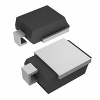
SM8S24AHE3/2D Vishay, SM8S24AHE3/2D Datasheet - Page 4

SM8S24AHE3/2D
Manufacturer Part Number
SM8S24AHE3/2D
Description
TVS 8W 24V 5% DO-218AB
Manufacturer
Vishay
Specifications of SM8S24AHE3/2D
Voltage - Reverse Standoff (typ)
24V
Voltage - Breakdown
26.7V
Power (watts)
8W
Polarization
Unidirectional
Mounting Type
Surface Mount
Package / Case
DO-218AB
Polarity
Unidirectional
Clamping Voltage
38.9 V
Operating Voltage
24 V
Breakdown Voltage
26.7 V
Peak Surge Current
170 A
Peak Pulse Power Dissipation
6600 W
Maximum Operating Temperature
+ 175 C
Minimum Operating Temperature
- 55 C
Dimensions
8.7(Max) mm W x 13.7(Max) mm L
Reverse Stand-off Voltage Vrwm
24V
Breakdown Voltage Range
26.7V To 29.5V
Clamping Voltage Vc Max
38.9V
Diode Configuration
Unidirectional
Peak Pulse Current Ippm
170A
Diode Case Style
DO-218AB
No. Of Pins
2
Rohs Compliant
Yes
Power Dissipation Pd
8W
Lead Free Status / RoHS Status
Lead free / RoHS Compliant
Available stocks
Company
Part Number
Manufacturer
Quantity
Price
Application Note
Vishay General Semiconductor
Two Groups of Load Dump TVS
There are two kinds of load dump TVS for the primary
protection of automotive electronics: EPI PAR TVS and
Non-EPI PAR TVS. Both product groups have similar
operating breakdown characteristics in reverse bias mode.
The difference is that EPI-PAR TVSs have low forward
voltage drop (V
non-EPI PAR TVSs have relatively high V
conditions. This characteristic is important to the reverse
voltage supplied to the power line. Most CMOS ICs and LSIs
have very poor reverse voltage capabilities.
The gates of MOSFETs are also weak in reverse voltage, at
- 1 V or lower. In the reversed power input mode, the voltage
of the power line is the same as the voltage of the TVS V
This reverse bias mode causes electronic circuit failure. The
low forward voltage drop of EPI PAR TVSs is a good solution
SECONDARY PROTECTION OF THE AUTOMOTIVE POWER LINE
The primary target of protection circuits in automotive
systems is high surge voltages, but the clamped voltage is
still high. Secondary protection is especially important in
24 V powertrains, such as found in trucks and vans. The
main reason for this is the maximum input voltages for most
Adding resistor R onto the power line reduces the
transient current, allowing smaller power-rating TVSs as the
secondary
microprocessor and logic circuits in electronic units are
150 mA to 300 mA, and the minimum output voltage of a
12 V battery is 7.2 V at - 18 °C, or 14.4 V for a 24 V battery
under the same conditions. In a 24 V battery under the
above conditions, the supply voltage at a 300 mA load is 8.4
V at R = 20 Ω, and 11.4 V at R = 10 Ω at a minimum voltage
of battery of 14.4 V (24 V battery voltage in - 18 °C).
www.vishay.com
4
protection.
F
) characteristics in forward mode, and
Transient Voltage Suppressors (TVS) for
DiodesAmericas@vishay.com, DiodesAsia@vishay.com,
Transient
Voltage
For technical questions within your region, please contact one of the following:
Current
Automotive Electronic Protection
+
Power
Line
requirements
F
under the same
Protection
Fig. 8 - Secondary Protection Circuit
Primary
for
F
Current Limiter
.
R
Clamped
Voltage
to this problem. Another method to protect circuits from
reversed power input is utilizing a polarity protection rectifier
into the power line, as shown in Figure 7. A polarity
protection rectifier should have sufficient forward current
ratings, and forward surge and reverse voltage capabilities.
regulators and DC/DC converter ICs for automotive
applications are 45 V to 60 V. For this kind of application,
using secondary protection, as shown in Figure 8, is
recommended.
Power rating of R = I
This supply voltage is higher than the minimum input
voltages for most voltage regulators and DC/DC converter
ICs.
V
V
V
I
R: Resistor value
L
L
L
min.
: Load current
: Voltage to load
=
Secondary
Protection
Power Input
: Minimum input voltage
(
Reverse
DiodesEurope@vishay.com
+
V
-
min.
⁄
(
V
Fig. 7 - Reverse Bias Status
min.
Current
2
R
⁄
I
L
Load
)
Clamped
)
Voltage
×
(
(
V
min.
TVS
⁄
Document Number: 88490
I
L
) R
V
–
F
Revision: 09-Aug-10
)
Protected
Load


