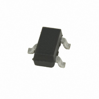
SPLV2.8HTG Littelfuse Inc, SPLV2.8HTG Datasheet - Page 2

SPLV2.8HTG
Manufacturer Part Number
SPLV2.8HTG
Description
TVS DIODE ARRAY 1CH 3.8PF SOT23
Manufacturer
Littelfuse Inc
Series
SPA™ SPLVr
Datasheet
1.SPLV2.8HTG.pdf
(4 pages)
Specifications of SPLV2.8HTG
Package / Case
SOT-23-3
Voltage - Reverse Standoff (typ)
2.8V
Voltage - Breakdown
3V
Power (watts)
400W
Polarization
Unidirectional
Mounting Type
Surface Mount
Clamping Voltage
5.7 V, 8.3 V, 7 V, 12.5 V, 0.3 V
Current Rating
24 A
Operating Voltage
2.8 V
Breakdown Voltage
3 V
Capacitance
5 pF
Termination Style
SMD/SMT
Operating Temperature Range
- 40 C to + 85 C
Clamping Voltage Vc Max
15V
Diode Case Style
SOT-23
No. Of Pins
3
Svhc
No SVHC (20-Jun-2011)
Diode Configuration
Unidirectional
Peak Pulse Current Ippm
24A
Reverse Stand-off Voltage Vrwm
2.8V
Rohs Compliant
Yes
Lead Free Status / RoHS Status
Lead free / RoHS Compliant
Lead Free Status / RoHS Status
Lead free / RoHS Compliant, Lead free / RoHS Compliant
Other names
F3530TR
Available stocks
Company
Part Number
Manufacturer
Quantity
Price
Part Number:
SPLV2.8HTG
Manufacturer:
LITTELFUSE/力特
Quantity:
20 000
Note:
CAUTION: Stresses above those listed in “Absolute Maximum Ratings” may cause
permanent damage to the device. This is a stress only rating and operation of the device
at these or any other conditions above those indicated in the operational sections of this
specification is not implied.
SPLV2.8 Series
Reverse Standoff Voltage
Reverse Breakdown Voltage
Snap Back Voltage
Reverse Leakage Current
Clamping Voltage
Clamping Voltage
Clamping Voltage
Clamping Voltage
Dynamic Resistance
ESD Withstand Voltage
Diode Capacitance
Electrical Characteristics (T
Absolute Maximum Ratings
Figure 2: Clamping Voltage vs. I
Peak Pulse Power (t
Peak Pulse Current (t
Operating Temperature
Storage Temperature
1
Parameter is guaranteed by design and/or device characterization.
14
12
10
8
6
4
2
0
0
Parameter
Parameter
1
1
1
1
1
P
=8/20μs)
P
Peak Pulse Current-I
1
=8/20μs)
10
OP
Symbol
V
I
R
V
= 25°C)
V
V
LEAK
C
RWM
V
DYN
ESD
BR
SB
C
D
-60 to 150
PP
-40 to 85
Rating
1
600
40
TVS Diode Arrays
Lightning Surge Protection - SPLV2.8 Series
PP
(V
I
I
I
PP
I
PP
(A)
PP
PP
C2
V
=24A, t
=24A, t
=5A, t
=5A, t
V
R
IEC61000-4-2 (Contact)
- V
=0V, f=1MHz (Pin 2 to 1)
R
=2.8V (Pin 2 or 3 to 1)
20
C1
IEC61000-4-2 (Air)
Test Conditions
) / (I
P
P
P
P
=8/20μs (Pin 3 to 1)
=8/20μs (Pin 2 to 1)
=8/20μs (Pin 3 to 1)
=8/20μs (Pin 2 to 1)
I
T
Units
I
PP2
I
=50mA
R
T
=2μA
W
ºC
ºC
≤1μA
A
- I
PP1
Revision: April 14, 2011
2
) (Pin 2 to 1)
122
Figure 1: Capacitance vs. Reverse Voltage
Figure 3: Pulse Waveform
(SPA
4.0
3.
3.0
2.
2.0
1.
1.0
0.
0.0
110%
100%
90%
80%
70%
60%
40%
30%
20%
10%
0.0
0%
0%
™
Min
±30
±30
3.0
2.8
0.0
Family of Products)
0.
.0
13.9
Typ
5.7
8.3
0.4
2.0
7 .0
Please refer to
10.0
1.0
DC Bias (V)
Time (μs)
Specifications are subject to change without notice.
www.littelfuse.com/SPA
Max
12.5
15.0
1 .0
2.8
8.5
2.5
7 .0
1
1.
20.0
Units
μA
kV
kV
pF
V
V
V
V
V
V
V
Ω
2.0
for current information.
2 .0
©2011 Littelfuse, Inc.
30.0
2.


