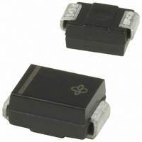
SMBJ10CA-E3/52 Vishay, SMBJ10CA-E3/52 Datasheet - Page 4

SMBJ10CA-E3/52
Manufacturer Part Number
SMBJ10CA-E3/52
Description
TVS BIDIRECT 600W 10V 5% SMB
Manufacturer
Vishay
Series
TransZorb®r
Specifications of SMBJ10CA-E3/52
Package / Case
DO-214AA, SMB
Power (watts)
600W
Polarization
Bidirectional
Voltage - Breakdown
11.1V
Voltage - Reverse Standoff (typ)
10V
Polarity
Bidirectional
Channels
1 Channel
Clamping Voltage
17 V
Operating Voltage
10 V
Breakdown Voltage
11.1 V to 12.3 V
Termination Style
SMD/SMT
Peak Surge Current
3.3 A
Peak Pulse Power Dissipation
600 W
Maximum Operating Temperature
+ 150 C
Minimum Operating Temperature
- 55 C
Dimensions
3.94(Max) mm W x 4.57(Max) mm L
Reverse Stand-off Voltage Vrwm
10V
Breakdown Voltage Range
11.1V To 12.3V
Clamping Voltage Vc Max
17V
Diode Configuration
Bidirectional
Peak Pulse Current Ippm
35.3A
Diode Case Style
DO-214AA
Mounting Type
Surface Mount
Number Of Elements
1
Package Type
SMB
Operating Temperature Classification
Military
Reverse Breakdown Voltage
11.1V
Reverse Stand-off Voltage
10V
Leakage Current (max)
10uA
Peak Pulse Current
35.3A
Test Current (it)
1mA
Operating Temp Range
-55C to 150C
Mounting
Surface Mount
Pin Count
2
Lead Free Status / RoHS Status
Lead free / RoHS Compliant
Lead Free Status / RoHS Status
Lead free / RoHS Compliant, Lead free / RoHS Compliant
Other names
SMBJ10CA-E3/5B
Available stocks
Company
Part Number
Manufacturer
Quantity
Price
Company:
Part Number:
SMBJ10CA-E3/52
Manufacturer:
VISHAY
Quantity:
35 000
Part Number:
SMBJ10CA-E3/52
Manufacturer:
VISHAY/威世
Quantity:
20 000
SMBJ5.0 thru SMBJ188CA
Vishay General Semiconductor
Note:
(1) Mounted on minimum recommended pad layout
Note:
(1) Automotive grade AEC Q101 qualified
RATINGS AND CHARACTERISTICS CURVES
(T
www.vishay.com
4
Figure 2. Pulse Power or Current vs. Initial Junction Temperature
THERMAL CHARACTERISTICS (T
PARAMETER
Typical thermal resistance, junction to ambient
Typical thermal resistance, junction to lead
ORDERING INFORMATION (Example)
PREFERRED P/N
SMBJ5.0A-E3/52
SMBJ5.0A-E3/5B
SMBJ5.0AHE3/52
SMBJ5.0AHE3/5B
A
= 25 °C unless otherwise noted)
100
100
10
0.1
75
50
25
0
0.1 µs
1
0
Figure 1. Peak Pulse Power Rating Curve
0.2 x 0.2" (5.0 x 5.0 mm)
25
Copper Pad Areas
1.0 µs
(1)
(1)
T
50
J
- Initial Temperature (°C)
t
d
10 µs
- Pulse Width (s)
75
UNIT WEIGHT (g)
PDD-Americas@vishay.com, PDD-Asia@vishay.com, PDD-Europe@vishay.com
100
For technical questions within your region, please contact one of the following:
0.096
0.096
0.096
0.096
100 µs
125
150
1.0 ms
175
(1)
PREFERRED PACKAGE CODE
A
10 ms
= 25 °C unless otherwise noted)
200
5B
5B
52
52
6000
1000
150
100
100
SYMBOL
50
10
0
R
R
0
1
θJA
θJL
BASE QUANTITY
Figure 4. Typical Junction Capacitance
t
d
V
3200
3200
750
750
WM
t
r
= 10 µs
V
Voltage V
Peak Value
I
Uni-Directional
Bi-Directional
Figure 3. Pulse Waveform
PPM
1.0
R
- Reverse Stand-Off Voltage (V)
, Measured at Stand-Off
t - Time (ms)
WM
Half Value -
I
VALUE
PPM
10
100
20
13" diameter plastic tape and reel
13" diameter plastic tape and reel
2.0
7" diameter plastic tape and reel
7" diameter plastic tape and reel
10/1000 µs Waveform
as defined by R.E.A.
T
Pulse Width (t
is defined as the Point
where the Peak Current
decays to 50 % of I
J
= 25 °C
I
DELIVERY MODE
2
PP
Document Number: 88392
T
f = 1.0 MHz
V
J
sig
= 25 °C
3.0
= 50 mVp-p
Measured at
Zero Bias
d
Revision: 04-Sep-07
)
100
PPM
UNIT
°C/W
°C/W
200
4.0


