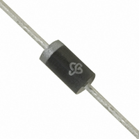
P6KE8.2A-E3/54 Vishay, P6KE8.2A-E3/54 Datasheet - Page 6

P6KE8.2A-E3/54
Manufacturer Part Number
P6KE8.2A-E3/54
Description
TVS 600W 8.2V 5% UNIDIR AXIAL
Manufacturer
Vishay
Series
TransZorb®r
Datasheet
1.P6KE10-E354.pdf
(7 pages)
Specifications of P6KE8.2A-E3/54
Voltage - Reverse Standoff (typ)
7.02V
Voltage - Breakdown
7.79V
Power (watts)
600W
Polarization
Unidirectional
Mounting Type
Through Hole
Package / Case
DO-204AC, DO-15, Axial
Polarity
Unidirectional
Channels
1 Channel
Clamping Voltage
12.1 V
Operating Voltage
7.02 V
Breakdown Voltage
7.79 V to 8.61 V
Termination Style
Axial
Peak Surge Current
49.6 A
Peak Pulse Power Dissipation
600 W
Maximum Operating Temperature
+ 185 C
Minimum Operating Temperature
- 65 C
Dimensions
3.6 mm Dia. x 3.6 (Max) mm W x 7.6 mm L
Reverse Stand-off Voltage Vrwm
7.02V
Breakdown Voltage Range
7.79V To 8.61V
Clamping Voltage Vc Max
12.1V
Diode Configuration
Unidirectional
Peak Pulse Current Ippm
49.6A
Lead Free Status / RoHS Status
Lead free / RoHS Compliant
Lead Free Status / RoHS Status
Lead free / RoHS Compliant, Lead free / RoHS Compliant
Other names
P6KE8.2A-E3/73
Available stocks
Company
Part Number
Manufacturer
Quantity
Price
Company:
Part Number:
P6KE8.2A-E3/54
Manufacturer:
VISHAY
Quantity:
500 000
P6KE6.8 thru P6KE540A
Vishay General Semiconductor
PACKAGE OUTLINE DIMENSIONS in inches (millimeters)
APPLICATION NOTE
This P6KE TVS series is a low cost commercial
product for use in applications where large voltage
transients can permanently damage voltage-sensitive
components.
The P6KE series device types are designed in a small
package size where power and space is a
consideration. They are characterized by their high
surge capability, extremely fast response time, and low
impedance, (R
nature of transients, and the variation of the
impedance
impedance, per se, is not specified as a parametric
value. However, a minimum voltage at low current
conditions (BV) and a maximum clamping voltage (V
at a maximum peak pulse current is specified.
www.vishay.com
6
100
0.1
10
0.001
1
Figure 7. Typical Transient Thermal Impedance
0.01
with
on
). Because of the unpredictable
t
p
0.1
respect
- Pulse Duration (s)
PDD-Americas@vishay.com, PDD-Asia@vishay.com, PDD-Europe@vishay.com
For technical questions within your region, please contact one of the following:
1
to
10
these
100
transients,
1000
0.300 (7.6)
0.230 (5.8)
1.0 (25.4)
1.0 (25.4)
MIN.
MIN.
DO-204AC (DO-15)
c
)
In some instances, the thermal effect (see V
Clamping Voltage) may be responsible for 50 % to
70 %. of the observed voltage differential when
subjected to high current pulses for several duty
cycles,
specification insignificant.
In case of a severe current overload or abnormal
transient beyond the maximum ratings, the Transient
Voltage Suppressor will initially fail 'short' thus tripping
the system's circuit breaker or fuse while protecting the
entire circuit. Curves depicting clamping voltage vs.
various current pulses are available from the factory.
Extended power curves vs. pulse time are also
available.
0.034 (0.86)
0.028 (0.71)
0.140 (3.6)
0.104 (2.6)
DIA.
DIA.
thus
making
a
maximum
Document Number: 88369
Revision: 22-Oct-08
impedance
c


