1N5908G ON Semiconductor, 1N5908G Datasheet - Page 2
1N5908G
Manufacturer Part Number
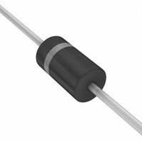
1N5908G
Description
TVS 1500W 6.2V UNIDIR AXIAL
Manufacturer
ON Semiconductor
Series
Mosorb™r
Type
Zenerr
Specifications of 1N5908G
Voltage - Reverse Standoff (typ)
5V
Voltage - Breakdown
6V
Power (watts)
1500W
Polarization
Unidirectional
Mounting Type
Through Hole
Package / Case
Axial
Number Of Elements
1
Polarity
Uni-Directional
Package Type
Case 41A-02
Operating Temperature Classification
Military
Reverse Breakdown Voltage
6V
Clamping Voltage
8.5V
Reverse Stand-off Voltage
5V
Leakage Current (max)
300uA
Peak Pulse Current
8A
Peak Pulse Power Dissipation
1500W
Test Current (it)
1mA
Operating Temp Range
-65C to 175C
Mounting
Through Hole
Pin Count
2
Operating Voltage
5 V
Breakdown Voltage
6 V
Termination Style
Axial
Peak Surge Current
120 A
Maximum Operating Temperature
+ 175 C
Minimum Operating Temperature
- 65 C
Dimensions
5.3 mm Dia. x 5.21 (Max) mm W x 9.5 mm L
Brand/series
1N5908 Series
Current, Surge
200 A
Primary Type
Transient Voltage Surge Suppressor
Termination
Solder
Voltage, Clamping
8.5 V
Lead Free Status / RoHS Status
Lead free / RoHS Compliant
For Use With
Industrial Equipment
Other names
1N5908G
1N5908GOS
1N5908GOS


Stresses exceeding Maximum Ratings may damage the device. Maximum Ratings are stress ratings only. Functional operation above the
Recommended Operating Conditions is not implied. Extended exposure to stresses above the Recommended Operating Conditions may affect
device reliability.
1. Nonrepetitive current pulse per Figure 4 and derated above T
2. 1/2 sine wave (or equivalent square wave), PW = 8.3 ms, duty cycle = 4 pulses per minute maximum.
*Bidirectional device will not be available in this device
3. Square waveform, PW = 8.3 ms, Non-repetitive duty cycle.
4. 1N5908 is JEDEC registered as a unidirectional device only (no bidirectional option)
5. A transient suppressor is normally selected according to the maximum working peak reverse voltage (V
6. V
7. Surge current waveform per Figure 4 and derate per Figure 2 of the General Data - 1500 W at the beginning of this group
ELECTRICAL CHARACTERISTICS
otherwise noted, V
MAXIMUM RATINGS
ELECTRICAL CHARACTERISTICS
Peak Power Dissipation (Note 1) @ T
Steady State Power Dissipation
Thermal Resistance, Junction-to-Lead
Forward Surge Current (Note 2) @ T
Operating and Storage Temperature Range
Symbol
V
greater than the dc or continuous peak operating voltage level.
V
I
RWM
V
(Note 4)
V
1N5908
PP
I
I
I
Device
BR
BR
R
T
F
C
F
measured at pulse test current I
@ T
Derated above T
Maximum Reverse Peak Pulse Current
Clamping Voltage @ I
Working Peak Reverse Voltage
Maximum Reverse Leakage Current @ V
Breakdown Voltage @ I
Test Current
Forward Current
Forward Voltage @ I
L
≤ 75°C, Lead Length = 3/8″
F
(Note 5)
(Volts)
V
= 3.5 V Max. @ I
RWM
5.0
L
= 75°C
Parameter
I
R
F
@ V
PP
(mA)
300
Rating
T
F
A
L
RWM
(Note 3) = 100 A)
= 25°C
T
≤ 25°C
at an ambient temperature of 25°C and minimum voltages in V
(T
(T
A
A
= 25°C unless
= 25°C unless otherwise noted, V
Min
6.0
V
BR
RWM
Breakdown Voltage
(Note 6) (Volts)
Nom
-
A
1N5908
= 25°C per Figure 2.
Max
2
-
(mA)
@ I
1.0
F
V
= 3.5 V Max. @ I
T
C
V
BR
@ I
Symbol
T
R
I
J
P
FSM
V
P
, T
qJL
PP
PK
RWM
D
Uni-Directional TVS
stg
8.5
= 120 A
F
(Note 3
I
F
V
BR
C
I
I
I
I
RWM
@ I
R
T
PP
(Volts) (Note 7)
are to be controlled.
- 65 to +175
)
V
= 53 A)
PP
), which should be equal to or
F
8.0
Value
1500
200
= 60 A
5.0
50
20
@ I
PP
7.6
V
mW/°C
= 30 A
°C/W
Unit
°C
W
W
A
Related parts for 1N5908G
Image
Part Number
Description
Manufacturer
Datasheet
Request
R

Part Number:
Description:
ON Semiconductor [VOLTAGE REGULATOR]
Manufacturer:
ON Semiconductor
Datasheet:
Part Number:
Description:
357-036-542-201 CARDEDGE 36POS DL .156 BLK LOPRO
Manufacturer:
ON Semiconductor
Datasheet:
Part Number:
Description:
357-036-542-201 CARDEDGE 36POS DL .156 BLK LOPRO
Manufacturer:
ON Semiconductor
Datasheet:
Part Number:
Description:
357-036-542-201 CARDEDGE 36POS DL .156 BLK LOPRO
Manufacturer:
ON Semiconductor
Datasheet:
Part Number:
Description:
357-036-542-201 CARDEDGE 36POS DL .156 BLK LOPRO
Manufacturer:
ON Semiconductor
Datasheet:
Part Number:
Description:
357-036-542-201 CARDEDGE 36POS DL .156 BLK LOPRO
Manufacturer:
ON Semiconductor
Datasheet:
Part Number:
Description:
357-036-542-201 CARDEDGE 36POS DL .156 BLK LOPRO
Manufacturer:
ON Semiconductor
Datasheet:
Part Number:
Description:
357-036-542-201 CARDEDGE 36POS DL .156 BLK LOPRO
Manufacturer:
ON Semiconductor
Datasheet:
Part Number:
Description:
357-036-542-201 CARDEDGE 36POS DL .156 BLK LOPRO
Manufacturer:
ON Semiconductor
Datasheet:
Part Number:
Description:
357-036-542-201 CARDEDGE 36POS DL .156 BLK LOPRO
Manufacturer:
ON Semiconductor
Datasheet:
Part Number:
Description:
357-036-542-201 CARDEDGE 36POS DL .156 BLK LOPRO
Manufacturer:
ON Semiconductor
Datasheet:
Part Number:
Description:
Manufacturer:
ON Semiconductor
Datasheet:
Part Number:
Description:
Manufacturer:
ON Semiconductor
Datasheet:
Part Number:
Description:
Manufacturer:
ON Semiconductor
Datasheet: