1SMB20AT3G ON Semiconductor, 1SMB20AT3G Datasheet - Page 2
1SMB20AT3G
Manufacturer Part Number
1SMB20AT3G
Description
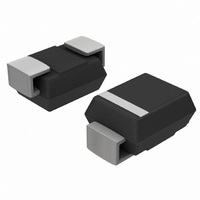
TVS 600W 20V UNIDIRECT SMB
Manufacturer
ON Semiconductor
Datasheet
1.1SMB7.0AT3G.pdf
(7 pages)
Specifications of 1SMB20AT3G
Voltage - Reverse Standoff (typ)
20V
Voltage - Breakdown
22.2V
Power (watts)
600W
Polarization
Unidirectional
Mounting Type
Surface Mount
Package / Case
DO-214AA, SMB
Polarity
Unidirectional
Clamping Voltage
32.4 V
Operating Voltage
20 V
Breakdown Voltage
23.35 V
Termination Style
SMD/SMT
Peak Surge Current
18.5 A
Peak Pulse Power Dissipation
600 W
Maximum Operating Temperature
+ 150 C
Minimum Operating Temperature
- 65 C
Dimensions
3.56 mm W x 4.32 mm L
Number Of Elements
1
Package Type
SMB
Operating Temperature Classification
Military
Reverse Breakdown Voltage
22.2V
Reverse Stand-off Voltage
20V
Leakage Current (max)
5uA
Peak Pulse Current
18.5A
Test Current (it)
1mA
Operating Temp Range
-65C to 150C
Mounting
Surface Mount
Pin Count
2
Reverse Stand-off Voltage Vrwm
20V
Clamping Voltage Vc Max
32.4V
Diode Configuration
Unidirectional
Diode Case Style
403A
No. Of Pins
2
Power Dissipation Pd
550mW
Breakdown Voltage Vbr
23.35V
Rohs Compliant
Yes
Lead Free Status / RoHS Status
Lead free / RoHS Compliant
Other names
1SMB20AT3GOSTR
Available stocks
Company
Part Number
Manufacturer
Quantity
Price
Company:

Part Number:
1SMB20AT3G
Manufacturer:
ON
Quantity:
15 000
Part Number:
1SMB20AT3G
Manufacturer:
ON/安森美
Quantity:
20 000


Stresses exceeding Maximum Ratings may damage the device. Maximum Ratings are stress ratings only. Functional operation above the
Recommended Operating Conditions is not implied. Extended exposure to stresses above the Recommended Operating Conditions may affect
device reliability.
1. 10 X 1000 ms, non−repetitive.
2. 1 in square copper pad, FR−4 board.
3. FR−4 board, using ON Semiconductor minimum recommended footprint, as shown in 403A case outline dimensions spec.
4. 1/2 sine wave (or equivalent square wave), PW = 8.3 ms, duty cycle = 4 pulses per minute maximum.
5. 1/2 sine wave (or equivalent square wave), PW = 8.3 ms,
MAXIMUM RATINGS
ELECTRICAL CHARACTERISTICS
otherwise noted, V
Peak Power Dissipation (Note 1) @ T
DC Power Dissipation @ T
Thermal Resistance from Junction−to−Lead
DC Power Dissipation (Note 3) @ T
Thermal Resistance from Junction−to−Ambient
Forward Surge Current (Note 4) @ T
Operating and Storage Temperature Range
Symbol
V
Measured Zero Lead Length (Note 2)
Derate Above 75°C
Derate Above 25°C
non−repetitive duty cycle.
V
I
RWM
V
V
I
PP
I
I
BR
R
T
F
C
F
Maximum Reverse Peak Pulse Current
Clamping Voltage @ I
Working Peak Reverse Voltage
Maximum Reverse Leakage Current @ V
Breakdown Voltage @ I
Test Current
Forward Current
Forward Voltage @ I
F
= 3.5 V Max. @ I
L
= 75°C
Parameter
F
PP
A
T
F
A
= 25°C
L
(Note 5) = 30 A)
= 25°C
= 25°C, Pulse Width = 1 ms
Rating
(T
A
= 25°C unless
RWM
http://onsemi.com
2
V
C
V
Symbol
BR
T
R
R
I
J
P
FSM
P
P
, T
qJA
V
qJL
PK
D
D
RWM
stg
Uni−Directional TVS
I
F
−65 to +150
I
I
I
I
R
T
PP
Value
0.55
600
226
100
3.0
4.4
40
25
V
F
mW/°C
mW/°C
°C/W
°C/W
Unit
°C
W
W
W
A
V
Related parts for 1SMB20AT3G
Image
Part Number
Description
Manufacturer
Datasheet
Request
R

Part Number:
Description:
ON Semiconductor [VOLTAGE REGULATOR]
Manufacturer:
ON Semiconductor
Datasheet:
Part Number:
Description:
357-036-542-201 CARDEDGE 36POS DL .156 BLK LOPRO
Manufacturer:
ON Semiconductor
Datasheet:
Part Number:
Description:
357-036-542-201 CARDEDGE 36POS DL .156 BLK LOPRO
Manufacturer:
ON Semiconductor
Datasheet:
Part Number:
Description:
357-036-542-201 CARDEDGE 36POS DL .156 BLK LOPRO
Manufacturer:
ON Semiconductor
Datasheet:
Part Number:
Description:
357-036-542-201 CARDEDGE 36POS DL .156 BLK LOPRO
Manufacturer:
ON Semiconductor
Datasheet:
Part Number:
Description:
357-036-542-201 CARDEDGE 36POS DL .156 BLK LOPRO
Manufacturer:
ON Semiconductor
Datasheet:
Part Number:
Description:
357-036-542-201 CARDEDGE 36POS DL .156 BLK LOPRO
Manufacturer:
ON Semiconductor
Datasheet:
Part Number:
Description:
357-036-542-201 CARDEDGE 36POS DL .156 BLK LOPRO
Manufacturer:
ON Semiconductor
Datasheet:
Part Number:
Description:
357-036-542-201 CARDEDGE 36POS DL .156 BLK LOPRO
Manufacturer:
ON Semiconductor
Datasheet:
Part Number:
Description:
357-036-542-201 CARDEDGE 36POS DL .156 BLK LOPRO
Manufacturer:
ON Semiconductor
Datasheet:
Part Number:
Description:
357-036-542-201 CARDEDGE 36POS DL .156 BLK LOPRO
Manufacturer:
ON Semiconductor
Datasheet:
Part Number:
Description:
Manufacturer:
ON Semiconductor
Datasheet:
Part Number:
Description:
Manufacturer:
ON Semiconductor
Datasheet:
Part Number:
Description:
Manufacturer:
ON Semiconductor
Datasheet: