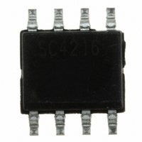
RCLAMP2502L.TBT Semtech, RCLAMP2502L.TBT Datasheet - Page 5

RCLAMP2502L.TBT
Manufacturer Part Number
RCLAMP2502L.TBT
Description
TVS ARRAY 800W 2.5V 2CH 8-SOIC
Manufacturer
Semtech
Series
RailClamp®r
Datasheet
1.RCLAMP2502L.TBT.pdf
(9 pages)
Specifications of RCLAMP2502L.TBT
Voltage - Reverse Standoff (typ)
2.5V
Voltage - Breakdown
2.7V
Power (watts)
800W
Polarization
2 Channel Array - Bidirectional
Mounting Type
Surface Mount
Package / Case
8-SOIC (3.9mm Width)
Lead Free Status / RoHS Status
Lead free / RoHS Compliant
Other names
RCLAMP2502LTR
Available stocks
Company
Part Number
Manufacturer
Quantity
Price
Company:
Part Number:
RCLAMP2502L.TBT
Manufacturer:
SEM
Quantity:
1 000
Device Connection Options for Protection of Two
High-Speed Data Lines
The RClamp2502L is designed to protect two high-
speed data lines (one differential pair) from transient
over-voltages which result from lightning and ESD.
Data line inputs/outputs are connected at pins 1 to 8,
and 4 to 5. The device is designed such that PCB
traces can remain unbroken and routed thru the
device as shown. Differential protection is achieved by
leaving pins 2, 3, 6, and 7 not connected.
Protecting Ethernet-based Systems to the Short-
Haul/Intrabuilding Lightning Immunity Requirements
of GR-1089
The Telcordia Technologies (Bellcore) GR-1089-CORE
specification defines a set of requirements for lightning
and AC power cross immunity for intrabuilding equip-
ment. The lightning tests are applied as ±800 volt
metallic (line-to-line) or ±1500 volt longitudinal (line-to-
ground) surges. The waveforms are defined with a rise
time of 2µs and a decay time of 10µs with a short
circuit current of 100A. One surge of positive and one
of negative polarity are applied. To pass the test, the
equipment must continue to operate after the test.
The combination of low clamping voltage, high surge
capability, and low loading capacitance makes the
RClamp2502L an ideal solution for protecting GbE
systems to the lightning immunity requirements of GR-
1089. In a typical system the RClamp2502L is
located on the PHY side of the transformer (see
schematic on next page). One device is required for
each transmit and receive line pair. This configuration
relies on the transformer isolation voltage to suppress
the 1500 volt common mode surge. While this ne-
gates the need for longitudinal line side protection, it is
important to make sure the resistor/capacitor termina-
tion networks are rated accordingly. During metalic
mode surges, energy will be transferred through the
magnetics until the transformer saturates. The
RClamp2502L will clamp the transferred voltage to a
safe level, protecting the Ethernet PHY. The amount of
energy will vary depending on the transformer, but will
be well within the surge handling capability of the
RClamp2502L. As always, the final design should be
verified with testing.
PROTECTION PRODUCTS
© 2009 Semtech Corp.
Applications Information
5
Line in
Line in
Pin 2, 3, 6, 7
Pin 1
Pin 4
Connection for Differential Protection
1
4
Circuit Diagram
(Line-to-Line)
RClamp2502L
5
8
www.semtech.com
Line out
Line out
Pin 8
Pin 5


