SM712.TCT Semtech, SM712.TCT Datasheet - Page 4
SM712.TCT
Manufacturer Part Number
SM712.TCT
Description
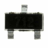
IC TVS ASYMM RS-485V 7/12V SOT23
Manufacturer
Semtech
Datasheet
1.SM712.TCT.pdf
(6 pages)
Specifications of SM712.TCT
Voltage - Reverse Standoff (typ)
12V
Voltage - Breakdown
13.3V
Power (watts)
400W
Polarization
2 Channel Array - Bidirectional
Mounting Type
Surface Mount
Package / Case
SOT-23-3
Lead Free Status / RoHS Status
Lead free / RoHS Compliant
Other names
SM712TR
Available stocks
Company
Part Number
Manufacturer
Quantity
Price
Company:

Part Number:
SM712.TCT
Manufacturer:
SEMTECH
Quantity:
60 000
Part Number:
SM712.TCT
Manufacturer:
SEMTECH/美国升特
Quantity:
20 000


Device Connection for Protection of Two RS-485 Data
Lines
EIA RS-485 specifies a ±7V ground difference between
devices on the bus. This permits the bus voltage to
range from +12V (5V + 7V) to -7V (0 - 7V).
The SM712 is designed to protect two RS-485 data
lines in extended common mode applications. The
SM712 may be used to protect devices from transient
voltages resulting from ESD, EFT, and lightning. The
device is designed with asymmetrical operating volt-
ages for optimum protection. The TVS diodes at pins 1
and 2 have a working voltage of 12 volts. These pins
are connected to the differential data line pairs. The
TVS diodes at pin 3 have a working voltage of 7 volts.
Pin 3 is connected to ground. The internal TVS diodes
of the SM712 will protect the transceiver input from
positive transient voltage spikes greater than 12V and
negative spikes greater than 7V.
A series current limiting resistor may be added in
applications requiring enhanced surge immunity.
Circuit Board Layout Recommendations.
Good circuit board layout is critical for the suppression
of fast rise-time transients such as ESD. The following
guidelines are recommended:
PROTECTION PRODUCTS
PROTECTION PRODUCTS
Applications Information
2004 Semtech Corp.
Place the SM712 near the input terminals or
connectors to restrict electromagnetic coupling.
Minimize the path length between the SM712 and
the protected line. This minimizes voltage over-
shoot due to parasitic inductance of board traces.
Use ground planes whenever possible.
Long, single trace ground conductors should be
avoided. The ground pin (Pin 3) should be con-
nected directly to a ground plane on the circuit
board for best results.
Minimize all conductive loops including power and
ground loops.
Never run critical signals near board edges.
4
RS-485 Common Mode Voltages
RS-485 Protection Circuit
www.semtech.com
SM712
Related parts for SM712.TCT
Image
Part Number
Description
Manufacturer
Datasheet
Request
R

Part Number:
Description:
Asymmetrical Tvs Diode For Extended Common-mode Rs-485
Manufacturer:
Semtech Corporation
Datasheet:

Part Number:
Description:
EVALUATION BOARD
Manufacturer:
Semtech
Datasheet:
Part Number:
Description:
EVALUATION BOARD
Manufacturer:
Semtech
Datasheet:
Part Number:
Description:
VOLTAGE SUPPRESSOR, TRANSIENT SEMTECH
Manufacturer:
Semtech
Datasheet:
Part Number:
Description:
HIGH VOLTAGE CAPACITORS MONOLITHIC CERAMIC TYPE
Manufacturer:
Semtech Corporation
Datasheet:
Part Number:
Description:
EZ1084CM5.0 AMP POSITIVE VOLTAGE REGULATOR
Manufacturer:
Semtech Corporation
Datasheet:
Part Number:
Description:
3.0 AMP LOW DROPOUT POSITIVE VOLTAGE REGULATORS
Manufacturer:
Semtech Corporation
Datasheet:
Part Number:
Description:
Manufacturer:
Semtech Corporation
Datasheet:
Part Number:
Description:
RailClamp Low Capacitance TVS Diode Array
Manufacturer:
Semtech Corporation
Datasheet:
Part Number:
Description:
Manufacturer:
Semtech Corporation
Datasheet:
Part Number:
Description:
Manufacturer:
Semtech Corporation
Datasheet:
Part Number:
Description:
Manufacturer:
Semtech Corporation
Datasheet: