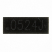
RCLAMP0524J.TCT Semtech, RCLAMP0524J.TCT Datasheet - Page 5

RCLAMP0524J.TCT
Manufacturer Part Number
RCLAMP0524J.TCT
Description
TVS ARRAY SLP2710P8 8-PIN
Manufacturer
Semtech
Series
RailClamp®r
Datasheet
1.RCLAMP0524J.TCT.pdf
(11 pages)
Specifications of RCLAMP0524J.TCT
Mfg Application Notes
TVS Diode AppNote SI07-12
Voltage - Reverse Standoff (typ)
5V
Voltage - Breakdown
6V
Power (watts)
150W
Polarization
4 Channel Array - Bidirectional
Mounting Type
Surface Mount
Package / Case
SLP2710P8
Lead Free Status / RoHS Status
Lead free / RoHS Compliant
Other names
RCLAMP0524JTR
Available stocks
Company
Part Number
Manufacturer
Quantity
Price
Company:
Part Number:
RCLAMP0524J.TCT
Manufacturer:
SEMTECH
Quantity:
840
Part Number:
RCLAMP0524J.TCT
Manufacturer:
SEMTECH/美国升特
Quantity:
20 000
Design Recommendations for HDMI Protection
Adding external ESD protection to HDMI ports can be
challenging. First ESD protection devices have an
inherent junction capacitance. However, adding even a
small amount of capacitance will cause the impedance
of the differential pair to drop. Second, large packages
and land pattern requirements cause discontinuities
that adversely affect signal integrity. The
RClamp0524J is specifically designed for protection of
high-speed interfaces such as HDMI. They present
<0.3pF capacitance between the pairs while being
rated to handle >±8kV ESD contact discharges
(>±15kV air discharge) as outlined in IEC 61000-4-2.
Each device is in a leadless SLP package that is less
than 1.1mm wide. They are designed such that the
traces flow straight through the device. The narrow
package and flow-through design reduces
discontinuities and minimizes impact on signal integrity.
This becomes even more critical as signal speeds
increase.
Pin Configuration
Figure 1 is an example of how to route the high speed
differential traces through the RClamp0524J. The
solid line represents the PCB trace. The PCB traces
are used to connect the pin pairs for each line (pin 1 to
pin 8, pin 2 to pin 7, pin 3 to pin 6, pin 4 to pin 5). For
example, line 1 enters at pin 1 and exits at Pin 8 and
the PCB trace connects pin 1 and 8 together. This is
true for lines connected at pins 2, 3, and 4 also.
Ground is connected at the center tabs. One large
ground pad should be used in lieu of two separate
pads.
TDR Measurements for HDMI
The combination of low capacitance, small package, and
flow-through design means it is possible to use these
devices to meet the HDMI impedance requirements of
100 Ohm ±15% without any PCB board modification.
Figures 3 and 4 show impedance test results for a TDR
risetime of 200ps and 100ps respectively, using a
Semtech evaluation board with 100 Ohm traces through-
out. Measurements were taken using a TDR method as
outlined in the HDMI Compliance Test Specification
(CTS). In each case, the device meets the HDMI CTS
PROTECTION PRODUCTS
© 2008 Semtech Corp.
Applications Information
5
SLP2710P8 Pin Configuration (Top View)
Figure 1. Flow through Layout Using
Figure 1. Flow through Layout Using
Figure 1. Flow through Layout Using
Figure 1. Flow through Layout Using
Figure 1. Flow through Layout Using
, 5
, 1
G
, 2
, 6
P
8
1
N
n i
, 7
, 3
D
4
8
12
12
11
11
10
10
9
9
8
8
7
7
6
6
5
5
4
4
3
3
2
2
1
1
7
2
R R R R R Clam
GND
GND
Clam
Clam
Clam
Clamp052
GND
GND
N (
1
1
o
p052
p052
p052
p0524J
n I
RClamp0524J
d I
O
e t
n I
u
e
n r
p
p t
n
r G
6
3
t u
f i t
4J 4J
4J 4J
l a
t u
u o
GND
GND
c i
C
L
n
L
t a
n o
n i
PRELIMINARY
n i
d
o i
s e
s e
n
5
4
e
n
www.semtech.com
t c
o i
) n


