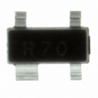
SR70.TCT Semtech, SR70.TCT Datasheet - Page 4

SR70.TCT
Manufacturer Part Number
SR70.TCT
Description
IC TVS ARRAY 2-LINE 300W SOT-143
Manufacturer
Semtech
Series
RailClamp®r
Datasheet
1.SR70.TCT.pdf
(6 pages)
Specifications of SR70.TCT
Voltage - Reverse Standoff (typ)
70V
Voltage - Breakdown
85V
Power (watts)
300W
Polarization
2 Channel Array - Unidirectional
Mounting Type
Surface Mount
Package / Case
SOT-143, SOT-143B, TO-253AA
Suppressor Type
Diode Arrays
Esd Protection Voltage
15KV@Air Gap/8KV@Contact Disc
Configuration
Dual
Mounting Style
Surface Mount
Clamping Voltage (max)
7VV
Working Voltage (max)
70VV
Leakage Current (max)
5uAA
Operating Temperature Min Deg. C
-55C
Operating Temperature Max Deg. C
125C
Product Length (mm)
3.04(Max)mm
Product Depth (mm)
1.4(Max)mm
Product Height (mm)
1.1mm
Pin Count
3 +Tab
Rad Hardened
No
Lead Free Status / RoHS Status
Lead free / RoHS Compliant
Other names
SR70TR
Available stocks
Company
Part Number
Manufacturer
Quantity
Price
Company:
Part Number:
SR70.TCT
Manufacturer:
Semtech
Quantity:
3 000
Part Number:
SR70.TCT
Manufacturer:
SEMTECH/美国升特
Quantity:
20 000
Device Connection Options for Protection of Two
High-Speed Data Lines
The SR70 is designed to protect two data lines from
transient over-voltages by clamping them to a fixed
reference. When the voltage on the protected line
exceeds the reference voltage (plus diode V
steering diodes are forward biased, conducting the
transient current away from the sensitive circuitry.
Data lines are connected at pins 2 and 3. The nega-
tive reference (REF1) is connected at pin 1. This pin
should be connected directly to a ground plane on the
board for best results. The path length is kept as short
as possible to minimize parasitic inductance.
The positive reference (REF2) is connected at pin 4.
The options for connecting the positive reference are
as follows:
1. To protect data lines and the power line, connect
2. In applications where no positive supply reference
PROTECTION PRODUCTS
Applications Information
2003 Semtech Corp.
pins 2 and 3 directly to the positive supply rail (V
In this configuration the data lines are referenced
to the supply voltage. An external TVS diode may
be added between the supply rail and ground in
order to prevent over-voltage on the supply rail.
is available, or complete supply isolation is desired,
an external TVS diode may be used as the refer-
ence. The steering diodes will begin to conduct
when the voltage on the protected line exceeds the
working voltage of the TVS (plus one diode drop).
F
) the
CC
).
4
Data Line and Power Supply Protection Using Vcc as
reference
SR70 Pin Configuration
1
2
4
3
www.semtech.com
SR70


