VESD05A1-02V-GS08 Vishay, VESD05A1-02V-GS08 Datasheet - Page 2
VESD05A1-02V-GS08
Manufacturer Part Number
VESD05A1-02V-GS08
Description
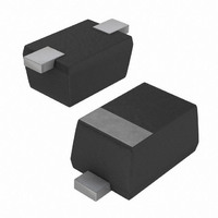
DIODE SGL ESD 5.0V SOD523
Manufacturer
Vishay
Series
VESD05A1-02Vr
Datasheet
1.VESD05A1-02V-GS08.pdf
(7 pages)
Specifications of VESD05A1-02V-GS08
Voltage - Reverse Standoff (typ)
5V
Voltage - Breakdown
6V
Power (watts)
192W
Polarization
Unidirectional
Mounting Type
Surface Mount
Package / Case
SOD-523
Polarity
Bidirectional
Channels
1 Channel
Clamping Voltage
12 V
Operating Voltage
5 V (Min)
Breakdown Voltage
6.8 V
Termination Style
SMD/SMT
Peak Surge Current
16 A
Peak Pulse Power Dissipation
192 W
Capacitance
130 pF
Maximum Operating Temperature
+ 125 C
Minimum Operating Temperature
- 40 C
Dimensions
0.9 mm W x 1.3 mm L x 0.7 mm H
Reverse Stand-off Voltage Vrwm
5V
Breakdown Voltage Range
6V To 7.5V
Clamping Voltage Vc Max
12V
Diode Configuration
Bidirectional
Peak Pulse Current Ippm
16A
Diode Case Style
SOD-523
No. Of Pins
2
Lead Free Status / RoHS Status
Lead free / RoHS Compliant
Lead Free Status / RoHS Status
Lead free / RoHS Compliant, Lead free / RoHS Compliant
Other names
751-1440-2
VESD05A1-02V-GS08GITR
VESD05A1-02V-GS08GITR
VESD05A1-02V-GS08GITR
VESD05A1-02V-GS08GITR


VESD05A1-02V
Vishay Semiconductors
BiAs-Mode (Bidirectional Asymmetrical protection mode)
With the VESD05A1-02V one signal- or data-lines (L1) can be protected against voltage transients. With pin 1
connected to ground and pin 2 connected to a signal- or data-line which has to be protected. As long as the
voltage level on the data- or signal-line is between 0 V (ground level) and the specified Maximum Reverse
Working Voltage (V
line. The protection device behaves like an open switch.
As soon as any positive transient voltage signal exceeds the break through voltage level of the protection
diode, the diode becomes conductive and shorts the transient current to ground. Now the protection device
behaves like a closed switch. The Clamping Voltage (V
plus the voltage drop at the series impedance (resistance and inductance) of the protection device.
Any negative transient signal will be clamped accordingly. The negative transient current is flowing in the
forward direction of the protection diode. The low Forward Voltage (V
the ground level.
Due to the different clamping levels in forward and reverse direction the VESD05A1-02V clamping behaviour
is Bidirectional and Asymmetrical (BiAs).
Electrical Characteristics
Ratings at 25 °C ambient temperature, unless otherwise specified
VESD05A1-02V
BiAs mode (between pin 1 and pin 2)
www.vishay.com
2
Protection paths
Reverse stand off voltage
Reverse current
Reverse break down voltage
Reverse clamping voltage
Forward clamping voltage
Capacitance
Parameter
L1
RWM
) the protection diode between data line and ground offers a high isolation to the ground
Number of lines which can be protected
at I
at I
For technical support, please contact: ESD-Protection@vishay.com
PP
PP
at I
at I
at I
= I
= I
PP
PP
PP
at V
Test conditions/remarks
at V
PPM
PPM
= 0.2 A; 8/20 µs test pulse
= 1 A; 8/20 µs test pulse
= 1 A; 8/20 µs test pulse
R
R
at I
= 16 A; 8/20 µs test pulse
= 16 A; 8/20 µs test pulse
= 2.5 V; f = 1 MHz
at I
at V
= 0 V; f = 1 MHz
R
R
R
= 1 mA
= 1 µA
= 5 V
C
) is defined by the BReakthrough Voltage (V
Symbol
V
N
V
RWM
V
V
C
C
V
V
V
lines
I
BR
R
C
C
F
F
F
D
D
F
) clamps the negative transient close to
Min.
5
6
< 0.1
10.5
0.88
Typ.
130
6.8
7.2
1.0
3.2
76
20280
Document Number 84702
Max.
150
7.5
8.5
1.1
1.5
4.5
12
1
1
Rev. 1.3, 27-Oct-08
BR
lines
Unit
µA
) level
pF
pF
V
V
V
V
V
V
V
Related parts for VESD05A1-02V-GS08
Image
Part Number
Description
Manufacturer
Datasheet
Request
R

Part Number:
Description:
357-036-542-201 CARDEDGE 36POS DL .156 BLK LOPRO
Manufacturer:
Vishay
Datasheet:
Part Number:
Description:
357-036-542-201 CARDEDGE 36POS DL .156 BLK LOPRO
Manufacturer:
Vishay
Datasheet:
Part Number:
Description:
357-036-542-201 CARDEDGE 36POS DL .156 BLK LOPRO
Manufacturer:
Vishay
Datasheet:
Part Number:
Description:
357-036-542-201 CARDEDGE 36POS DL .156 BLK LOPRO
Manufacturer:
Vishay
Datasheet:
Part Number:
Description:
357-036-542-201 CARDEDGE 36POS DL .156 BLK LOPRO
Manufacturer:
Vishay
Datasheet:
Part Number:
Description:
357-036-542-201 CARDEDGE 36POS DL .156 BLK LOPRO
Manufacturer:
Vishay
Datasheet:
Part Number:
Description:
357-036-542-201 CARDEDGE 36POS DL .156 BLK LOPRO
Manufacturer:
Vishay
Datasheet:
Part Number:
Description:
357-036-542-201 CARDEDGE 36POS DL .156 BLK LOPRO
Manufacturer:
Vishay
Datasheet:
Part Number:
Description:
357-036-542-201 CARDEDGE 36POS DL .156 BLK LOPRO
Manufacturer:
Vishay
Datasheet:
Part Number:
Description:
357-036-542-201 CARDEDGE 36POS DL .156 BLK LOPRO
Manufacturer:
Vishay
Datasheet:
Part Number:
Description:
357-036-542-201 CARDEDGE 36POS DL .156 BLK LOPRO
Manufacturer:
Vishay
Datasheet:
Part Number:
Description:
357-036-542-201 CARDEDGE 36POS DL .156 BLK LOPRO
Manufacturer:
Vishay
Datasheet:
Part Number:
Description:
357-036-542-201 CARDEDGE 36POS DL .156 BLK LOPRO
Manufacturer:
Vishay
Datasheet:
Part Number:
Description:
357-036-542-201 CARDEDGE 36POS DL .156 BLK LOPRO
Manufacturer:
Vishay
Datasheet:
Part Number:
Description:
357-036-542-201 CARDEDGE 36POS DL .156 BLK LOPRO
Manufacturer:
Vishay
Datasheet: