595D156X96R3A2T Vishay, 595D156X96R3A2T Datasheet - Page 12
595D156X96R3A2T
Manufacturer Part Number
595D156X96R3A2T
Description
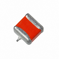
CAP TANT 15UF 6.3V 10% SMD
Manufacturer
Vishay
Series
TANTAMOUNT® 595Dr
Type
Conformal Coatedr
Datasheet
1.595D107X96R3C2T.pdf
(13 pages)
Specifications of 595D156X96R3A2T
Capacitance
15µF
Voltage - Rated
6.3V
Tolerance
±10%
Esr (equivalent Series Resistance)
1.700 Ohm
Operating Temperature
-55°C ~ 125°C
Mounting Type
Surface Mount
Package / Case
1507 (3718 Metric)
Size / Dimension
0.146" L x 0.071" W (3.70mm x 1.80mm)
Height
0.055" (1.40mm)
Manufacturer Size Code
A
Features
General Purpose
Voltage Rating, Dc
6.3V
Capacitor Dielectric Type
TANTALUM ELECTROLYTIC
Tolerance,
10%
Tolerance, -
10%
Temp, Op. Min
-55(DEGREE C)
Temp,
ROHS COMPLIANT
Voltage Rating
6.3 Volts
Esr
1.7 Ohms
Operating Temperature Range
- 55 C to + 85 C
Dimensions
1.8 mm W x 3.7 mm L
Mfr Case Code
A Case
Product
Tantalum Solid Standard Grade - Other Various
Dissipation Factor Df
6
Leakage Current
0.9 uAmps
Termination Style
SMD/SMT
Lead Free Status / RoHS Status
Lead free / RoHS Compliant
Lead Spacing
-
Lead Free Status / Rohs Status
Details


Notes:
1.
2.
Document Number: 40007
Revision: 16-Dec-05
B 0
Double Pitch
Note: Metric dimensions will govern. Dimensions in inches are rounded and for reference only.
TAPE AND REEL PACKAGING in inches [millimeters]
Tape Size
12 mm
12 mm
(Top View)
8 mm
For Tape Feeder
Reference only
including draft.
Concentric around B
(Note 5)
A
ends of the terminals extending from the component body
and/or the body dimensions of the component. The
clearance between the ends of the terminals or body of the
component to the sides and depth of the cavity (A
must be within 0.002" [0.05 mm] minimum and 0.020" [0.50
mm] maximum. The clearance allowed must also prevent
rotation of the component within the cavity of not more than
20 degrees.
Tape with components shall pass around radius "R" without
damage. The minimum trailer length may require additional
length to provide R minimum for 12 mm embossed tape for
reels with hub diameters approaching N minimum.
A 0
(Note 6)
B Max.
0
1
B
0
[0.600]
K
20˚ Maximum
Component Rotation
0.024
Max.
0
are determined by the maximum dimensions to the
B
Typical
Component
Cavity
Center Line
Typical
Component
Center Line
(Note 6)
0.004 [0.10]
1
0.179
[4.55]
0.323
0.323
[8.2]
[8.2]
Max.
T
(Max.)
Max.
0
2
K 0
Top
Cover
Tape
D
(Note 5)
1
0.039
0.059
0.059
[1.0]
[1.5]
[1.5]
Deformation
Between
Embossments
(Min.)
Top
Cover
Tape
Allowable Camber to be 0.039/3.937 [1/100]
Non-Cumulative Over 9.843 [250.0]
For technical questions, contact: tantalum@vishay.com
TANTAMOUNT® Conformal Coated,
0.138 ± 0.002
0.217 ± 0.002
0.453 ± 0.004
Center Lines
of Cavity
[11.5 ± 0.03]
[3.5 ± 0.05]
[5.5 ± 0.05]
3.937 [100.0]
Solid Tantalum Chip Capacitors
0.059 + 0.004 - 0.0
[1.5 + 0.10 - 0.0]
F
0.039 [1.0]
USER DIRECTION OF FEED
Max.
0.9843 [250.0]
(T op View)
Camber
A
0.157 ± 0.004
0.157 ± 0.004
0.315 ± 0.004
0
Maximum CV
0
[4.0 ± 0.10]
[4.0 ± 0.10]
[8.0 ± 0.10]
B
0.039 [1.0]
Max.
0
P 1
K
B 0
0.157 ± 0.004
[4.0 ± 0.10]
0
P
Tape
)
1
DIRECTION OF FEED
3.
4.
5.
6.
Cathode (-)
0.079 ± 0.002
[2.0 ± 0.05]
Maximum
Cavity Size
(Note 1)
Anode (+)
10 Pitches Cumulative
Tolerance on Tape
± 0.008 [0.200]
R (Min.)
(Note 2)
0.984
[25.0]
1.181
[30.0]
1.181
[30.0]
This dimension is the flat area from the edge of the sprocket
hole to either the outward deformation of the carrier tape
between the embossed cavities or to the edge of the cavity
whichever is less.
This dimension is the flat area from the edge of the carrier
tape opposite the sprocket holes to either the outward
deformation of the carrier tape between the embossed
cavity or to the edge of the cavity whichever is less.
The embossment hole location shall be measured from the
sprocket hole controlling the location of the embossment.
Dimensions of embossment location and hole location shall
be applied independent of each other.
B1 dimension is a reference dimension for tape feeder
clearance only.
D Min. For Components
0.079 x 0.047 [2.0 x 1.2] and Larger .
(Note 5)
Tape and Reel Specifications: All case sizes are
available on plastic embossed tape per EIA-481-1.
Tape reeling per IEC 286-3 is also available. Standard
reel diameter is 7" [178mm]. 13" [330mm] reels are
available and recommended as the most cost effective
packaging method.
The most efficient packaging quantities are full reel
increments on a given reel diameter. The quantities
shown allow for the sealed empty pockets required to
be in conformance with EIA-481-1. Reel size and
packaging orientation must be specified in the Vishay
Sprague part number.
0.030 [0.75]
Min. (Note 3)
1
0.030 [0.75]
Min. (Note 4)
Embossment
T
2
0.098
0.256
0.256
[2.5]
[6.5]
[6.5]
(Max.)
F
0.069 ± 0.004
[1.75 ± 0.10]
W
0.315 + 0.012 - 0.004
[8.0 + 0.3 - 0.1]
0.472 ± 0.012
0.945 ± 0.012
[12.0 ± 0.30]
[24.0 ± 0.30]
Vishay Sprague
(Side or Front Sectional Vie w )
20˚
W
Maximum
Component
Rotation
www.vishay.com
595D
(Note 1)
A
0
B
0
K
0
12
Related parts for 595D156X96R3A2T
Image
Part Number
Description
Manufacturer
Datasheet
Request
R

Part Number:
Description:
357-036-542-201 CARDEDGE 36POS DL .156 BLK LOPRO
Manufacturer:
Vishay
Datasheet:
Part Number:
Description:
357-036-542-201 CARDEDGE 36POS DL .156 BLK LOPRO
Manufacturer:
Vishay
Datasheet:
Part Number:
Description:
357-036-542-201 CARDEDGE 36POS DL .156 BLK LOPRO
Manufacturer:
Vishay
Datasheet:
Part Number:
Description:
357-036-542-201 CARDEDGE 36POS DL .156 BLK LOPRO
Manufacturer:
Vishay
Datasheet:
Part Number:
Description:
357-036-542-201 CARDEDGE 36POS DL .156 BLK LOPRO
Manufacturer:
Vishay
Datasheet:
Part Number:
Description:
357-036-542-201 CARDEDGE 36POS DL .156 BLK LOPRO
Manufacturer:
Vishay
Datasheet:
Part Number:
Description:
357-036-542-201 CARDEDGE 36POS DL .156 BLK LOPRO
Manufacturer:
Vishay
Datasheet:
Part Number:
Description:
357-036-542-201 CARDEDGE 36POS DL .156 BLK LOPRO
Manufacturer:
Vishay
Datasheet:
Part Number:
Description:
357-036-542-201 CARDEDGE 36POS DL .156 BLK LOPRO
Manufacturer:
Vishay
Datasheet:
Part Number:
Description:
357-036-542-201 CARDEDGE 36POS DL .156 BLK LOPRO
Manufacturer:
Vishay
Datasheet:
Part Number:
Description:
357-036-542-201 CARDEDGE 36POS DL .156 BLK LOPRO
Manufacturer:
Vishay
Datasheet:
Part Number:
Description:
357-036-542-201 CARDEDGE 36POS DL .156 BLK LOPRO
Manufacturer:
Vishay
Datasheet:
Part Number:
Description:
357-036-542-201 CARDEDGE 36POS DL .156 BLK LOPRO
Manufacturer:
Vishay
Datasheet:
Part Number:
Description:
357-036-542-201 CARDEDGE 36POS DL .156 BLK LOPRO
Manufacturer:
Vishay
Datasheet:
Part Number:
Description:
357-036-542-201 CARDEDGE 36POS DL .156 BLK LOPRO
Manufacturer:
Vishay
Datasheet: