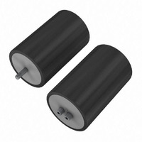
ALS30A222MF400 Kemet, ALS30A222MF400 Datasheet - Page 2

ALS30A222MF400
Manufacturer Part Number
ALS30A222MF400
Description
CAP ALUM 2200UF 400V SCREW TERM
Manufacturer
Kemet
Series
Evox Rifa ALS30r
Datasheet
1.ALS30A102KE400.pdf
(7 pages)
Specifications of ALS30A222MF400
Capacitance
2200µF
Voltage Rating
400V
Tolerance
±20%
Lifetime @ Temp.
19000 Hrs @ 85°C
Operating Temperature
-40°C ~ 85°C
Features
General Purpose
Ripple Current
11.2A
Esr (equivalent Series Resistance)
62.0 mOhm
Impedance
44 mOhm
Mounting Type
Chassis Mount
Package / Case
Radial, Can - Screw Terminals
Size / Dimension
2.598" Dia (66.00mm)
Height
4.134" (105.00mm)
Lead Spacing
1.122" (28.50mm)
Esr
62 mOhms
Operating Temperature Range
- 40 C to + 85 C
Diameter
66 mm
Length
105 mm
Product
Aluminum Electrolytic Capacitors
Termination Style
Screw
Test Frequency
100 Hz
Lead Free Status / RoHS Status
Lead free / RoHS Compliant
Surface Mount Land Size
-
Lead Free Status / Rohs Status
Lead free / RoHS Compliant
Other names
399-5632
case Polarity
Due to the presence of electrolyte in the capacitor the aluminium can and stud mounting will essentially be at the same polarity as the
negative terminal. We recommend that the stud and can are insulated (see accessories for insulating nuts).
terminals options
* preferred options in bold
terminations
Aluminium inserts with M5 threads as standard, max. torque 2NM. Optional M6 threaded inserts have a max. torque 4NM. Max.
torque for stud mounting M8:4NM and
* Dimensions Lt will change dependant on terminal style.
dimensions table als30 (sleeved) mm
terminal styles a, r
term.
code
style
case
MF
ND
QC
QD
QH
DA
DB
DE
DF
KE
NF
NP
NT
QP
QT
KF
M
a*
a*
C
G
R
J
fig. 1
V
DT
thread
±1
36
36
36
36
51
51
66
77
77
77
77
90
90
90
90
90
d
m5
m5
M6
M6
M6
M5
M5
105
105
105
105
146
220
146
220
TD
±2
52
62
82
82
75
67
75
98
l
t - mm
height
±0.5
5.5
7.14
5.5
6.35
3.17
7.14
5.5
111.5
110.5
110.5
110.5
150.5
224.5
103.5
149.5
223.5
Z
58.5
67.5
87.5
86.5
79.5
71.5
79.5
lt*
±1
Safety Vent
c, g, J, m
S
terminal styles a (ø36mm only),
fig. 2
dia. - dt
±0.5
12.8
12.8
12.8
12.8
22.2
22.2
28.5
31.8
31.8
31.8
31.8
31.8
31.8
31.8
31.8
31.8
±0.5
mm
s
13
13
17
17
15
8
8
V
M12:8NM.
±0.5
7.14
7.14
7.14
7.14
5.5
5.5
5.5
5.5
5.5
5.5
5.5
5.5
5.5
5.5
5.5
5.5
DT
t
thread depth
minimum
td - mm
10
10
10
11.8
10
10
13.7
13.7
15.8
mm thrEad
TD
8.8
19
19
19
19
25
25
25
25
25
v
8
8
8
8
“+” SIGN
M12
M12
M12
M12
M12
M12
M12
M12
M12
M12
M12
M12
M8
M8
M8
M8
m
sPEcification
drawing
fig.1
fig.2
Fig.2
Fig.2
Fig.2
Fig.2
Fig.1
S
±1
12
12
12
12
16
16
16
16
16
h
16
16
16
16
16
16
16
Z=10mm
ø36mm only
Z=13mm
T (measured
from deck
surface)
V3/H2/UTE2736
V3/H2/UTE2736
V3/H2/UTE2736
V3/H2/UTE2736
V10/UTE2738
V4/UTE2737
V4/UTE2737
mounting
als30
clamp mounting
cliP
V11
V11
V11
V11
V90
V90
V90
V90
V90
Lt
L
BHC and Evox Rifa
wEight grams
nom.
1450
1345
2000
115
140
220
300
505
495
690
960
615
690
900
75
90
ØD
Electrolytic Capacitors
terminal style
a
•
•
•
•
•
•
•
•
•
•
•
•
•
•
•
•
als31
stud mounting
c
•
•
•
•
•
•
•
•
•
•
g J
•
•
•
•
H
als30 85°c
•
•
•
•
•
•
•
•
•
M
m r
•
•
•
•
•
•
•
•
43


