78253/55MC Murata Power Solutions Inc, 78253/55MC Datasheet - Page 4
78253/55MC
Manufacturer Part Number
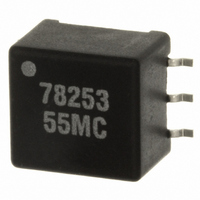
78253/55MC
Description
XFRMR 5V IN/OUT MAX 253 SMD
Manufacturer
Murata Power Solutions Inc
Series
78253r
Type
Compatible Converter Transformersr
Datasheet
1.7825355C.pdf
(5 pages)
Specifications of 78253/55MC
Inductance
830µH
Primary Voltage Rating
3.3 V
Secondary Voltage Rating
5 V
Mounting Style
SMD/SMT
Dimensions
12.7 mm L x 8.89 mm W x 6.35 mm H
Product
Toroidal Power Transformers
Height
6.35 mm
Length
12.7 mm
Number Of Outputs
2
Operating Temperature Range
- 40 C to + 85 C
Termination Style
Solder Pad
Turns Ratio
1:1:31
Width
8.89 mm
Current Rating
200mA
Power Rating
1W
Inductor Type
Toroidal
Dc Resistance Max
1.5ohm
Leakage Inductance
1µH
Isolation Voltage
1500V
No. Of Pins
6
Mounting Type
PCB Surface
Rohs Compliant
Yes
Lead Free Status / RoHS Status
Contains lead / RoHS Compliant
For Use With/related Products
MAX253
Lead Free Status / Rohs Status
Compliant
Other names
811-1270-5
Available stocks
Company
Part Number
Manufacturer
Quantity
Price
Company:

Part Number:
78253/55MC
Manufacturer:
C&D
Quantity:
1 000
Company:
Part Number:
78253/55MC-R
Manufacturer:
MURATA
Quantity:
10 000


TECHNICAL NOTES
ISOLATION
‘Hi Pot Test’, ‘Flash Tested’, ‘Withstand Volt-
age’, ‘Proof Voltage’, ‘Dielectric Withstand
Voltage’ & ‘Isolation Test Voltage’ are all terms
that relate to the same thing, a test voltage,
applied for a specifi ed time, across a compo-
nent designed to provide electrical isolation, to
verify the integrity of that isolation.
All products in this series are 100% production
tested at their stated isolation voltage.
A question commonly asked is, “What is the
continuous voltage that can be applied across
the part in normal operation?”
For a part holding no specifi c agency approv-
als both input and output should normally be
maintained within SELV limits i.e. less than
42.4V peak, or 60VDC. The isolation test
voltage represents a measure of immunity to
transient voltages and the part should never
be used as an element of a safety isolation
system. The part could be expected to function
correctly with several hundred volts offset
applied continuously across the isolation bar-
rier; but then the circuitry on both sides of the
barrier must be regarded as operating at an
unsafe voltage and further isolation/insulation
systems must form a barrier between these
circuits and any user-accessible circuitry ac-
cording to safety standard requirements.
TYPICAL CHARACTERISTICS (VOLTAGE CURVES) continued
www.murata-ps.com
VOLTAGE
110
105
100
110
105
100
90
95
90
95
-50
-50
-25
-25
Temperature (°C)
Temperature (°C)
0
78253/35(M)VC
0
78253/35(M)C
REPEATED HIGH-VOLTAGE
ISOLATION TESTING
It is well known that repeated high-voltage
isolation testing of a barrier component can
actually degrade isolation capability, to a
lesser or greater degree depending on ma-
terials, construction and environment. This
series has toroidal isolation transformers,
with no additional insulation between pri-
mary and secondary windings of enameled
wire. While parts can be expected to with-
stand several times the stated test voltage,
the isolation capability does depend on the
wire insulation. Any material, including this
enamel (typically polyurethane) is suscep-
tible to eventual chemical degradation when
subject to very high applied voltages thus
implying that the number of tests should be
strictly limited. We therefore strongly advise
against repeated high voltage isolation test-
ing, but if it is absolutely required, that the
voltage be reduced by 20% from specifi ed
test voltage.
This consideration equally applies to agency
recognized parts rated for better than
functional isolation where the wire enamel
insulation is always supplemented by a
further insulation system of physical spacing
or barriers.
25
25
50
50
75
75
100
100
VOLTAGE DEVIATION
All specifi cations typical at T
1 For further information, please visit www.murata-ps.com/rohs
SOLDERING INFORMATION
110
105
100
Pin fi nish
Peak wave solder temperature
Peak refl ow temperature
110
105
100
TUBE OUTLINE DIMENSIONS
95
90
95
90
-50
-50
0.023±0.005
(0.60±0.15)
Technical enquiries - email: mk@murata-ps.com, tel:
-25
-25
0.22 (5.50)
0.16 (4.00)
MAX253 Compatible Converter Transformers
Temperature (°C)
Temperature (°C)
0
78253/55(M)C
78253/55(M)VC
0
A
Unless otherwise stated all dimensions in inches(mm) ±0.01 (0.25).
=25°C
25
25
1
50
50
0.62 (15.70)
Tube length: 18.3±0.08 (465±2). Tube quantity: 50.
(10.95)
(3.80)
0.43
0.15
78253 Series
75
75
Tube material: Antistatic coated clear pvc.
KMP_78253C_C03 Page 4 of 5
100
100
Matte tin
300˚C for 10 seconds
220˚C
+44 (0)1908 615232
(12.95)
0.51
Related parts for 78253/55MC
Image
Part Number
Description
Manufacturer
Datasheet
Request
R

Part Number:
Description:
XFRMR 3.3V IN 5V OUT MAX 253 SMD
Manufacturer:
Murata Power Solutions Inc
Datasheet:

Part Number:
Description:
XFRMR 5V IN/OUT MAX 253 SMD
Manufacturer:
Murata Power Solutions Inc
Datasheet:

Part Number:
Description:
XFRMR 5V IN/OUT MAX 253 DIP
Manufacturer:
Murata Power Solutions Inc
Datasheet:

Part Number:
Description:
Transformers MAX253 CNVR XFRMR 3.3Vin 5Vout 1500VDC
Manufacturer:
Murata Power Solutions Inc
Datasheet:
Part Number:
Description:
Transformers 5Vin 5Vout 200mA 4000Vdc 1:1.33 turn
Manufacturer:
Murata Power Solutions Inc
Datasheet:

Part Number:
Description:
XFRMR 3.3V IN 5V OUT MAX 253 DIP
Manufacturer:
Murata Power Solutions Inc
Datasheet:

Part Number:
Description:
XFRMR 5V IN/OUT MAX 253 DIP
Manufacturer:
Murata Power Solutions Inc
Datasheet:
Part Number:
Description:
Transformers MAX253 CNVR XFRMR
Manufacturer:
Murata Power Solutions Inc
Datasheet:
Part Number:
Description:
Transformers MAX253 CNVR XFRMR
Manufacturer:
Murata Power Solutions Inc
Datasheet:
Part Number:
Description:
Transformers 253 SMT CNVR XFRMR
Manufacturer:
Murata Power Solutions Inc
Datasheet:
Part Number:
Description:
Transformers 5Vin 5Vout 200mA 4000Vdc 1:1.33 turn
Manufacturer:
Murata Power Solutions Inc
Datasheet:

Part Number:
Description:
POWER SUPPLY
Manufacturer:
Murata Power Solutions Inc
Datasheet:

Part Number:
Description:
DPM LED MINI 2VDC 3.5DIG LP RED
Manufacturer:
Murata Power Solutions Inc
Datasheet:

Part Number:
Description:
CONV DC/DC 1W 5VIN 5VOUT SIP SGL
Manufacturer:
Murata Power Solutions Inc
Datasheet:

Part Number:
Description:
CONV DC/DC 1W 5VIN 3.3V SIP SGL
Manufacturer:
Murata Power Solutions Inc
Datasheet: