HC3-SFD-K Panasonic Electric Works, HC3-SFD-K Datasheet - Page 4
HC3-SFD-K
Manufacturer Part Number
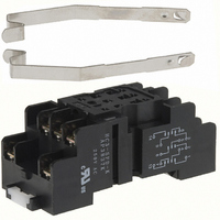
HC3-SFD-K
Description
SOCKET SCRW W/CLIP DIN HC3 RELAY
Manufacturer
Panasonic Electric Works
Series
HCr
Type
Socketr
Datasheet
1.HC-BRACKET.pdf
(8 pages)
Specifications of HC3-SFD-K
Number Of Positions
11
Mounting Type
DIN Rail
Termination Style
Screw Terminal
Features
Mounting Hardware
For Use With/related Products
HC3 Relays
For Use With
HC3-HL-DC6V-F - RELAY PWR 3PDT 7A 6VDC W/LEDHC3-HL-DC48V-F - RELAY PWR 3PDT 7A 48VDC W/LEDHC3-HL-DC24V-F - RELAY PWR 3PDT 7A 24VDC W/LEDHC3-HL-DC12V-F - RELAY PWR 3PDT 7A 12VDC W/LEDHC3-HL-DC100V-F - RELAY PWR 3PDT 7A 100VDC W/LEDHC3-HL-AC6V-F - RELAY PWR 3PDT 7A 6VAC W/LEDHC3-HL-AC48V-F - RELAY PWR 3PDT 7A 48VAC W/LEDHC3-HL-AC24V-F - RELAY PWR 3PDT 7A 24VAC W/LEDHC3-HL-AC240V-F - RELAY PWR 3PDT 7A 240VAC W/LEDHC3-HL-AC12V-F - RELAY PWR 3PDT 7A 12VAC W/LEDHC3-HL-AC120V-F - RELAY PWR 3PDT 7A 120VAC W/LEDHC3-H-DC6V-F - RELAY PWR 3PDT 7A 6VDC PLUG-INHC3-H-DC48V-F - RELAY PWR 3PDT 7A 48VDC PLUG-INHC3-H-DC100V-F - RELAY PWR 3PDT 7A 100VDC PLUG-INHC3-H-AC6V-F - RELAY PWR 3PDT 7A 6VAC PLUG-INHC3-H-AC48V-F - RELAY PWR 3PDT 7A 48VAC PLUG-INHC3-H-AC24V-F - RELAY PWR 3PDT 7A 24VAC PLUG-INHC3-H-AC240V-F - RELAY PWR 3PDT 7A 240VAC PLUG-INHC3-H-AC12V-F - RELAY PWR 3PDT 7A 12VAC PLUG-INHC3-H-AC120V-F - RELAY PWR 3PDT 7A 120VAC PLUG-INHC3-H-AC115V-F - RELAY PWR 3PDT 7A 115VAC PLUG-INHC3-HL-AC100V-F - RELAY PWR 3PDT 7A 100VAC PLUG INHC3-H-AC100V-F - RELAY PWR 3PDT 7A 100VAC PLUG IN255-2765 - RELAY PWR 7A 3PDT 24VDC PLUG-INHC3-H-DC12V-F - RELAY PWRT 7A 3PDT 12VDC PLUG-IN
Lead Free Status / RoHS Status
Lead free / RoHS Compliant
Other names
255-1840
HC3-SFD-K
HC3-SFD-K


HC
2. Specifications
Notes: In accordance with the Electrical Appliance and Material Safety Law, you cannot exceed a voltage of 150V AC when using the 4 Form C type. For more information,
3. Switching capacity and expected life
1) Electrical (at 20 cpm)
2) Mechanical (at 180 cpm)
Min. 5 10
Contact
Rating
Electrical
characteristics
Mechanical
characteristics
Expected life
Conditions
Unit weight
Characteristics
4 Form C (twin)
1 Form C
2 Form C
3 Form C
4 Form C
please inquire.
*1 This value can change due to the switching frequency, environmental conditions and desired reliability level, therefore it is recommended to check this with the
*2 For the AC coil types, the operate/release time will differ depending on the phase.
*3 The upper operation ambient temperature limit is the maximum temperature that can satisfy the coil temperature rise value.
Voltage
Load
actual load.
Refer to 6. Conditions for operation, transport and storage mentioned in AMBIENT ENVIRONMENT.
7
(AC coil type); Min. 10
Arrangement
Contact pressure
Initial contact resistance, max
Contact material
Nominal switching capacity
(resistive load)
Max. switching power
(resistive load)
Max. switching voltage
Max. switching current
Nominal operating power
Min. switching capacity
(Reference value)*
Insulation resistance (Initial)
Breakdown
voltage
(Initial)
Temperature rise (at 70 C
Operate time (at 20 C
Release time (at 20 C
Shock
resistance
Vibration
resistance
Mechanical
Electrical (resistive load)
Conditions for operation,
transport and storage*
Max. Operating speed
125V AC
10A
7A
5A
7A
5A
3A
7A
5A
5A
3A
2A
3A
—
Item
Resistive (cos
Between open
contacts
Between contact
sets
Between contact
and coil
Functional
Destructive
Functional
Destructive
1
3
68
68
8
F)*
(DC coil type)
F)*
158
2
2
F)
250V AC
= 1)
10A
7A
5A
7A
5A
3A
7A
5A
5A
3A
2A
3A
All Rights Reserved © COPYRIGHT Matsushita Electric Works, Ltd.
—
1 Form C
Approx. 0.294N{30gf} Approx. 0.147N{15gf} Approx. 0.147N{15gf} Approx. 0.098N{10gf} Approx. 0.127N{13gf}
Max. 30 m (By voltage drop 6 V DC 1A)
Ag alloy (cd free) + Au flash
10A 250V AC
2,500VA
250VAC
10A
AC (50Hz): 1.3VA, AC (60Hz): 1.2VA, DC: 0.9 to 1.1W
1mA 1V DC
Min. 1,000M
Measurement at same location as “Initial breakdown voltage” section.
700 Vrms for 1min. (Detection current: 10mA.)
700 Vrms for 1min. (Detection current: 10mA.)
2,000 Vrms for 1min. (Detection current: 10mA.)
Max. 80 C (By resistive method, nominal voltage)
Max. 20ms (Nominal voltage applied to the coil, excluding contact bounce time.)
Max. 20ms (Nominal voltage applied to the coil, excluding contact bounce time.) (without diode)
Min. 196 m/s
Min. 980 m/s
10 to 55 Hz at double amplitude of 1 mm (Detection time: 10 s.)
10 to 55 Hz at double amplitude of 2 mm
Min. 5 10
Min. 2 10
(at 20 cpm)
Ambient temperature: –50 C to +70 C
Humidity: 5 to 85% R.H. (Not freezing and condensing at low temperature)
20 cpm (at max. rating)
Approx. 30g
AC
7
5
: AC coil type (at 180 cpm); Min. 10
1.06 oz
2
2
(Half-wave pulse of sine wave: 11 ms; detection time: 10 s.)
(Half-wave pulse of sine wave: 6 ms.)
(at 500V DC)
125V AC
3.5A
2.5A
1.5A
3.5A
0.5A
5A
3A
2A
2A
1A
1A
—
—
Inductive (cos
2 Form C
7A 250V AC
1,750VA
7A
Min. 2 10
(at 20 cpm)
5
250V AC
–58 F to +158 F
0.4)
2.5A
1.5A
1.5A
0.8A
0.4A
0.8A
3A
2A
1A
2A
1A
—
—
8
: DC coil type (at 180 cpm)
3 Form C
7A 250V AC
1,750VA
7A
Min. 10
(at 20 cpm)
Specifications
5
(without LED); –50 C to +60 C
Resistive
30V DC
3A
3A
3A
3A
3A
—
—
—
—
—
—
—
—
4 Form C
AgNi type + Au clad
5A 250V AC
1,250VA
5A
Min. 2 10
(at 20 cpm)
DC
5
Inductive
30V DC
0.6A
0.4A
0.4A
1A
—
—
—
—
—
—
—
—
—
–58 F to +140 F
4 Form C (twin)
3A 250V AC
750VA
3A
100 A 1V DC
Min. 2 10
(at 20 cpm)
Expected life
Min. 2 10
Min. 5 10
Min. 2 10
Min. 5 10
Min. 2 10
Min. 5 10
Min. 2 10
Min. 5 10
Min. 2 10
Min. 10
Min. 10
Min. 10
Min. 10
5
(with LED)
6
6
5
6
5
5
5
5
5
5
5
5
5
Related parts for HC3-SFD-K
Image
Part Number
Description
Manufacturer
Datasheet
Request
R

Part Number:
Description:
SOCKET PCB W/CLIP FOR HC3 RELAY
Manufacturer:
Panasonic Electric Works
Datasheet:

Part Number:
Description:
SOCKET SLD TAB W/CLIP HC3 RELAY
Manufacturer:
Panasonic Electric Works
Datasheet:
Part Number:
Description:
SOCKET SCREW FRONT WIRE/CLIP HC3
Manufacturer:
Panasonic Electric Works
Datasheet:

Part Number:
Description:
Relay Sockets & Hardware SOCKET WRAP-WIRNG/ CLIP HC3 RELAY
Manufacturer:
Panasonic
Datasheet:
Part Number:
Description:
Relay Sockets & Hardware 3 Form C 110VDC PCB Type
Manufacturer:
Panasonic
Datasheet:
Part Number:
Description:
Relay Sockets & Hardware 3 Form C 240VAC PCB Type
Manufacturer:
Panasonic
Datasheet:
Part Number:
Description:
Relay Sockets & Hardware 3 Form C 12VDC PCB Type
Manufacturer:
Panasonic
Datasheet:
Part Number:
Description:
Relay Sockets & Hardware 3 Form C 24VAC PCB Type
Manufacturer:
Panasonic
Datasheet:
Part Number:
Description:
Relay Sockets & Hardware 3 Form C 24VDC Plug_in with LED
Manufacturer:
Panasonic
Datasheet:
Part Number:
Description:
Relay Sockets & Hardware 3 Form C 12VAC PCB Type
Manufacturer:
Panasonic
Datasheet:

Part Number:
Description:
CONN SOCKET P4 .4MM 50POS SMD
Manufacturer:
Panasonic Electric Works
Datasheet:
Part Number:
Description:
CONN SOCKET .8MM 16POS SMD
Manufacturer:
Panasonic Electric Works
Datasheet:
Part Number:
Description:
CONN HEADER .8MM 16POS SMD
Manufacturer:
Panasonic Electric Works
Datasheet:
Part Number:
Description:
CONN SOCKET .8MM 20POS SMD
Manufacturer:
Panasonic Electric Works
Datasheet:
Part Number:
Description:
CONN SOCKET .8MM 20POS SMD
Manufacturer:
Panasonic Electric Works
Datasheet: