TXS2-24V Panasonic Electric Works, TXS2-24V Datasheet - Page 7
TXS2-24V
Manufacturer Part Number
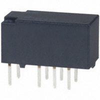
TXS2-24V
Description
RELAY 1A 24VDC 70MW PCB
Manufacturer
Panasonic Electric Works
Series
TX-Sr
Specifications of TXS2-24V
Relay Type
General Purpose
Circuit
DPDT (2 Form C)
Contact Rating @ Voltage
1A @ 30VDC
Coil Type
Standard
Coil Current
2.9mA
Coil Voltage
24VDC
Control On Voltage (max)
19.2 VDC
Control Off Voltage (min)
2.4 VDC
Mounting Type
Through Hole
Termination Style
PC Pin
Brand/series
TX-S Series
Contact Form
DPDT
Current, Rating
1 A
Diameter, Mounting
0.039 in. Dia. (Hole)
Dielectric Rating
1000 MW @ 500 VDC
Dimensions
0.591 in. L x 0.291 in. W x 0.323 in. H
Function
Sensitive
Latch Type
Single Side Stable
Material, Contact
Gold-Clad Silver Alloy
Number Of Pins
8
Power, Rating
30 W
Standards
UL, CSA
Temperature, Operating, Maximum
70 °C
Temperature, Operating, Minimum
-40 °C
Termination
Solder
Voltage, Control
24 VDC
Voltage, Rating
30 VDC
Lead Free Status / RoHS Status
Lead free / RoHS Compliant
Other names
255-2334-5
TXS2-24V
TXS2-24V
Available stocks
Company
Part Number
Manufacturer
Quantity
Price


Schematic (Top view)
NOTES
1. Packing style
1) The relay is packed in a tube with the
relay orientation mark on the left side, as
shown in the figure below.
2) Tape and reel packing (surface-mount
terminal type)
(1) Tape dimensions
(i) SA type
(ii) SL type
(iii) SS type
(2) Dimensions of plastic reel
Relay polarity bar
(Z type)
Stopper (gray)
(Deenergized condition)
Relay polarity bar
(Z type)
Relay polarity bar
(Z type)
Single side stable
.512 dia.
Direction indication
13 dia.
Relays
Relays
Relays
Orientation (indicates PIN No.1) stripe
12
1
.079
Tape coming out direction
Tape coming out direction
2.0
Tape coming out direction
10 9 8
3 4 5
.059
.059
.059
1.5
1.5
1.5
+0.1
+.004
+0.1
+.004
+0.1
+.004
0
0
0
0
0
0
21 dia.
.827 dia.
dia.
dia.
dia.
dia.
dia.
dia.
16.0
.630
.630
.630
16.0
16.0
.079
.079
.079
2.0
2.0
2.0
10.0
A
.157
.157
.157
(Reset condition)
4.0
4.0
4.0
10.0
.394
1 coil latching
Direction indication
.394
C
D
.315
B
8.0
11.5
.453
Stopper (green)
12
1.75
.069
15.5
.610
15.5
.610
1
24.0
.945
11.5
.453
24.0
.945
11.5
.453
24.0
.945
80 dia.
3.150 dia.
1.75
.069
1.75
.069
380 dia.
14.961 dia.
15.5
.610
All Rights Reserved © COPYRIGHT Panasonic Electric Works Co., Ltd.
mm
mm
mm
mm
10 9 8
0.3
.012
0.3
.012
3 4 5
0.3
.012
.362
10.8
.425
10.8
.425
9.2
.016
.016
inch
inch
0.4
inch
inch
0.4
.016
0.4
0.2
.008
0.2
.008
0.2
.008
2 coil latching (L2)
2. Automatic insertion
To maintain the internal function of the
relay, the chucking pressure should not
exceed the values below.
Chucking pressure in the direction A:
4.9 N {500gf} or less
Chucking pressure in the direction B:
9.8 N {1 kgf} or less
Chucking pressure in the direction C:
9.8 N {1 kgf} or less
Please chuck the
Avoid chucking the center of the relay.
In addition, excessive chucking pressure
to the pinpoint of the relay should be
avoided.
(Reset condition)
Direction indication
For general cautions for use,
please refer to the “Cautions for
use of Signal Relays” or “General
Application Guidelines”.
12
1
10 9 8 7
3 4 5 6
A
C
2 coil latching (LT)
Direction indication
portion.
(Reset condition)
12
1
B
10 9 8 7
3 4 5 6
TX-S
Related parts for TXS2-24V
Image
Part Number
Description
Manufacturer
Datasheet
Request
R

Part Number:
Description:
RELAY LATCH 1A 12VDC 70MW PCB
Manufacturer:
Panasonic Electric Works
Datasheet:

Part Number:
Description:
RELAY TELCOM 1A DPDT 4.5VDC PCB
Manufacturer:
Panasonic Electric Works
Datasheet:
Part Number:
Description:
RELAY LATCH 1A 4.5VDC 70MW PCB
Manufacturer:
Panasonic Electric Works
Datasheet:
Part Number:
Description:
RELAY 1A 9VDC 50MW PCB
Manufacturer:
Panasonic Electric Works
Datasheet:
Part Number:
Description:
RELAY LATCH 1A 24VDC 150MW PCB
Manufacturer:
Panasonic Electric Works
Datasheet:
Part Number:
Description:
RELAY 1A 6VDC 50MW PCB
Manufacturer:
Panasonic Electric Works
Datasheet:
Part Number:
Description:
RELAY TELCOM 1A DPDT 12VDC PCB
Manufacturer:
Panasonic Electric Works
Datasheet:
Part Number:
Description:
RELAY 1A 3VDC 50MW PCB
Manufacturer:
Panasonic Electric Works
Datasheet:

Part Number:
Description:
RELAY 1A DPDT 4.5VDC SELF CLINCH
Manufacturer:
Panasonic Electric Works
Datasheet:

Part Number:
Description:
RELAY LATCH 1A DPDT 12VDC PCB
Manufacturer:
Panasonic Electric Works
Datasheet:

Part Number:
Description:
CONN SOCKET P4 .4MM 50POS SMD
Manufacturer:
Panasonic Electric Works
Datasheet:

Part Number:
Description:
CONN SOCKET .8MM 16POS SMD
Manufacturer:
Panasonic Electric Works
Datasheet:
Part Number:
Description:
CONN HEADER .8MM 16POS SMD
Manufacturer:
Panasonic Electric Works
Datasheet:
Part Number:
Description:
CONN SOCKET .8MM 20POS SMD
Manufacturer:
Panasonic Electric Works
Datasheet:
Part Number:
Description:
CONN SOCKET .8MM 20POS SMD
Manufacturer:
Panasonic Electric Works
Datasheet: