DEMO908AP64 Freescale Semiconductor, DEMO908AP64 Datasheet - Page 8
DEMO908AP64
Manufacturer Part Number
DEMO908AP64
Description
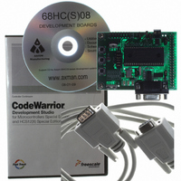
BOARD DEMO FOR 908AP64
Manufacturer
Freescale Semiconductor
Type
Microcontrollerr
Datasheet
1.DEMO908AP64E.pdf
(16 pages)
Specifications of DEMO908AP64
Contents
Board, CDs, Cable, Filter
Processor To Be Evaluated
MC68HC908AP
Data Bus Width
16 bit
Interface Type
RS-232
Silicon Manufacturer
Freescale
Core Architecture
HC08
Core Sub-architecture
HC08
Silicon Core Number
MC68HC908
Silicon Family Name
HC08AP
Kit Contents
Demo Board, Cables, Software, Guides
Rohs Compliant
No
For Use With/related Products
MC68HC908AP Family
Lead Free Status / RoHS Status
Contains lead / RoHS non-compliant


D E M O 9 0 8 A P 6 4
Three option jumper blocks and 3 cut-traces setup module operation. Enabling an associated
option requires installing a jumper, or shunt, across the appropriate header pins so that both
pins are connected via the jumper. Removing the shunt disables the associated option. A cut-
trace option can be disabled by cutting the circuit trace between the cut-trace component pads
with a razor knife. Install a 0805 SMT 0-ohm resistor or modification wire with a soldering iron
to re-enable the option if needed.
POWER SUPPLY
Input power may be applied by external connection to a 2 position terminal block and 3.3V
regulator or directly from connector J1. The input supply is selected by the PWR_SEL option.
TB1 – Terminal Block
The TB1 terminal block allows external voltage to be supplied to the module. Input voltage
should be limited to +5VDC and +16VDC; +9VDC is typical. The terminal block is a 3.55mm,
screw-type, connector that accepts a maximum 18 AWG wire. An on-board voltage regulator
(VR1) converts the input voltage to the +3.3VDC used by the module.
Figure 1: TB1 Terminal Block Connector
Connector J1
Connector J1 is a 40-pin, surface-mount, socket header mounted on the bottom of the module.
The connector is mounted over plated-through holes in the PCB. The socket is a pass-through
type socket designed to allow header insertion from either the top or bottom. This provides
maximum flexibility in connecting the module to an expansion environment or test equipment.
Connector J1 provides access to all MCU signals.
Power may be supplied to the module through pins J1-1 (+V) and J1-3 (GND). Use of this op-
tion requires voltage input regulated at +3.3VDC. This input is connected directly to the mod-
ule power and ground planes. Care should be exercised not to over-drive this input. J1 can
also be used to source power from the on-board regulator to external modules.
PWR_SEL option header determines how power is routed to and from the module.
+5VDC -
+16VDC
GND
J1
+
2 Position, Screw-
Type Terminal Block
8
MCU_PORT
J U N E
2 8 ,
2 0 0 4
The
Related parts for DEMO908AP64
Image
Part Number
Description
Manufacturer
Datasheet
Request
R

Part Number:
Description:
Manufacturer:
STMicroelectronics
Datasheet:

Part Number:
Description:
DEMO BOARD FOR HMC6042/HMC1041Z
Manufacturer:
Honeywell Microelectronics & Precision Sensors

Part Number:
Description:
DEMO BOARD FOR HMC1042L/HMC1041Z
Manufacturer:
Honeywell Microelectronics & Precision Sensors
Datasheet:

Part Number:
Description:
KIT DEMO 4 SENSOR CHAN RS232
Manufacturer:
VTI Technologies
Datasheet:


Part Number:
Description:
DEMO: DC Power Supply, 32 Volts, 3 Amps
Manufacturer:
Tektronix
Part Number:
Description:
DEMO: Programmable DC Power Supply, 32 Volts, 3 Amps
Manufacturer:
Tektronix

Part Number:
Description:
Manufacturer:
Freescale Semiconductor, Inc
Datasheet:
Part Number:
Description:
Manufacturer:
Freescale Semiconductor, Inc
Datasheet:
Part Number:
Description:
Manufacturer:
Freescale Semiconductor, Inc
Datasheet:
Part Number:
Description:
Manufacturer:
Freescale Semiconductor, Inc
Datasheet:
Part Number:
Description:
Manufacturer:
Freescale Semiconductor, Inc
Datasheet:
Part Number:
Description:
Manufacturer:
Freescale Semiconductor, Inc
Datasheet:
Part Number:
Description:
Manufacturer:
Freescale Semiconductor, Inc
Datasheet:
Part Number:
Description:
Manufacturer:
Freescale Semiconductor, Inc
Datasheet: