27297 Parallax Inc, 27297 Datasheet
27297
Specifications of 27297
Available stocks


Related parts for 27297


27297 Summary of contents
Page 1
...
Page 2
... HomeWork Board, Parallax, and the Parallax logo are trademarks of Parallax Inc. If you decide to use trademarks of Parallax Inc. on your web page or in printed material, you must state that "(trademark trademark of Parallax Inc.”, “upon the first appearance of the trademark name in each printed document or web page ...
Page 3
... Parallax products. Parallax Inc. is also not responsible for any personal damage, including that to life and health, resulting from use of any of our products. You take full responsibility for your BASIC Stamp application, no matter how life-threatening it may be ...
Page 4
...
Page 5
Preface......................................................................................................... iii Author’s Note ................................................................................................................. iii Getting the Most from StampWorks................................................................................v Steps to Success ............................................................................................................v Preparing the StampWorks Lab ................................................................... 1 StampWorks Kit Contents...............................................................................................1 Setting Up the Hardware and Software ..........................................................................2 Notes on Using Integrated Circuits in StampWorks Experiments...................................9 Programming ...
Page 6
Moving Forward ......................................................................................... 93 Experiment #14: Scanning and Debouncing Multiple Inputs ........................................94 Experiment #15: Counting Events ................................................................................98 Experiment #16: Frequency Measurement ................................................................101 Experiment #17: Advanced Frequency Measurement ...............................................106 Experiment #18: A Light Controlled Theremin............................................................109 Experiment #19: Sound Effects (SFX)........................................................................112 Experiment ...
Page 7
Preface AUTHOR’S NOTE Dear friends, It seems like ages ago that Ken Gracey handed me a new prototyping and development board and asked, “What do you think we could do with this?” That board, of course, was the original NX-1000 ...
Page 8
Among the changes that affect this edition of language: PBASIC 2.5. For those that come from a PC programming background, PBASIC 2.5 will make the transition to embedded programming a bit easier to deal with. And what I’m especially excited ...
Page 9
GETTING THE MOST FROM STAMPWORKS Before you get started, you’ll want to have a copy of the Reference Manual (version 2.1 or higher) handy – either printed or in PDF (available as a free download from www.parallax.com). Through the course ...
Page 10
Oftentimes we will rely on what we’ve previously worked through as support for a new experiment. Taken one at a time, the experiments are not difficult and if you work through them methodically, you’ll find your ...
Page 11
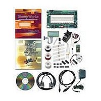
... PDB for use in the experiments that follow. Once this is done, you’ll be able to move through the experiments smoothly, and when you’ve completed StampWorks you’ll be ready for just about any project you can imagine. StampWorks Lab Kit Contents #27297 (parts and quantities subject to change without notice) Stock Code # ...
Page 12
SETTING UP THE HARDWARE AND SOFTWARE To set up the StampWorks lab for experiments, you’ll need the following items: Professional Development Board • • BASIC Stamp 2 module 12-volt wall pack (2.1 mm, center-positive plug) • Programming cable (serial or ...
Page 13
Note: For USB programming, make sure that you have the latest FDTI VCP (Virtual Com Port) driver. Step-by-step installation instructions of the VCP driver may be obtained via the StampWorks Product Page http at www.parallax.com. Computer System Requirements You will ...
Page 14
Preparing the Breadboard In the center of the PDB is a solderless breadboard where we will build circuits that are not integral to the PDB lab board itself (a variety of components are included in the StampWorks kit). It’s important ...
Page 15
If the breadboard was X-Rayed, we would see the internal connections and the breaks in the Vdd and Vss rails that need to be connected. Here’s a view of the breadboard’s internal connections: Start by setting your wire stripper for ...
Page 16
If you’ve measured and cut carefully, this “U” shaped wire will plug comfortably into the ground rail at sockets 29 and 32. This will create a single ground rail. Repeat this process with black wire for the bottom-most rail. Then, ...
Page 17
Final Checkout With the BASIC Stamp module installed and the breadboard prepared it is time for a final checkout before proceeding to the experiments. If you haven’t done so already, connect a programming cable (serial or USB) between your PC ...
Page 18
Now run the program. If all went well the program will be downloaded to the BASIC Stamp module and a Debug Terminal window will appear error occurs, check the following items: Is the BASIC Stamp module plugged into ...
Page 19
NOTES ON USING INTEGRATED CIRCUITS IN STAMPWORKS EXPERIMENTS There are two ways to draw integrated circuits (ICs schematic: One way is considered “chip-centric” in which I/O pins appear in the schematic according to their physical location on the ...
Page 20
...
Page 21
Programming Essentials CONTENTS OF A WORKING PROGRAM BASIC Stamp Syntax and Reference Manual In Sections the introduced to the BASIC Stamp, its architecture, and the concepts of variables and constants. In this section, we’ll introduce the ...
Page 22
BRANCHING – REDIRECTING PROGRAM FLOW A branching instruction is one that causes the flow of the program to change from its linear path. In other words, when the program encounters a branching instruction, it will, in almost all cases, not ...
Page 23
Start: IF (condition) THEN statement 1 statement 2 statement 3 ENDIF Note that the code statements are nested in an IF-THEN-ENDIF structure which does not require a branch label. If the condition evaluates as False, the program will continue at ...
Page 24
When index is zero, the program will branch to Label_0, when index is one the program will branch to Label_1 and so on. Related to BRANCH is ON-GOTO, in fact, it can serve as direct replacement: ON index GOTO Label_0, ...
Page 25
In the second example, the loop statements will run at least once, even if the condition evaluates as False. As you can see, the strength of DO-LOOP is that it simplifies how and where the condition testing occurs. DO-LOOP adds ...
Page 26
The STEP option of FOR-NEXT is used when the loop needs to count in increments other than one. If, for example, the loop needed to count even numbers, the code would look something like this: FOR counter = 2 TO ...
Page 27
Critical_Task: statement(s) RETURN Task_1: statement(s) RETURN Task_2: statement(s) RETURN Task_3: statement(s) RETURN With this type of program the code section at Critical_Task is interleaved between the other tasks. And by placing all task code into discrete subroutines, they can be ...
Page 28
...
Page 29
The Elements of PBASIC Style Like most versions of the BASIC programming language, PBASIC is very forgiving and the compiler enforces no particular formatting style. So long as the source code is syntactically correct, it will compile and download to ...
Page 30
Use Meaningful Names Be verbose when naming constants, variables, and program labels. The compiler will allow names characters long. Using meaningful names will reduce the number of comments and make your programs easier to read, debug ...
Page 31
Variable Type Definitions Conserve BASIC Stamp user RAM by declaring the variable type required to hold the expected values of the variable. bitValue VAR nibValue VAR byteValue VAR wordValue VAR 8. Program Labels Begin program labels with an uppercase ...
Page 32
Indent Nested Code Nesting blocks of code improves readability and helps reduce the introduction of errors. Indenting each level with two spaces is recommended to make the code readable without taking up too much space. Main: ..DO ....FOR testLoop ...
Page 33
Be Generous With White Space White space (spaces and blank lines) has no effect on compiler or BASIC Stamp performance generous with it to make listings easier to read. As suggested in #8 above, allow at least ...
Page 34
T9600 CON #CASE BS2PX T1200 CON T2400 CON T9600 CON #ENDSELECT The StampWorks files (available for download from www.parallax.com) include a blank programming template (Template.BS2) that will help you get started writing organized code. It you to follow ...
Page 35
Time to Experiment LEARN THE PROGRAMMING CONCEPTS What follows is a series of programming experiments that you can build and run with your StampWorks lab. The purpose of these experiments is to teach programming concepts and the use of external ...
Page 36
EXPERIMENT #1: FLASH AN LED LEDs are everywhere; virtually every piece of electronic equipment that provides some indication to a user can or does use LEDs. experiment is to flash an LED with the BASIC Stamp, as flashing LEDs are ...
Page 37
Program: SW21-EX01-Flash_LED.BS2: ' {$STAMP BS2} ' {$PBASIC 2.5} ' -----[ Program Description ]--------------------------------------------- ' ' Flashes an LED connected to P0. ' any BS2-family module. ' -----[ I/O Definitions ]------------------------------------------------- AlarmLed PIN 0 ' -----[ Constants ]------------------------------------------------------- FlashTm CON 500 ...
Page 38
For example, this: HIGH 0 … actually performs the same function as: DIR0 = 1 OUT0 = 1 but does it with just one line of code. important aspect of microcontroller programming, and when we can save code space we ...
Page 39
EXPERIMENT #2: FLASH AN LED (ADVANCED) Now that we’ve got things moving, let’s step up a bit and explore an advanced approach to flashing an LED. The method revealed in this experiment provides the best in program readability and ease-of-maintenance. ...
Page 40
Reset: Strobe = IsOff OUTPUT Strobe ' -----[ Program Code ]---------------------------------------------------- Main: DO Strobe = IsOn PAUSE FlashOn Strobe = IsOff PAUSE FlashOff LOOP Behind the Scenes The version of the LED blinker gets to the core of the hardware ...
Page 41
The main program loop is handled with the DO-LOOP construct, and separate on- and off-times are provided for flashing the LED. As ...
Page 42
Write Code like a Pro This version of the LED blinker is how a professional programmer would approach the task. Why? What if you were asked to write a program that required several LEDs and you assumed that they were ...
Page 43
EXPERIMENT #3: DISPLAY A COUNTER WITH LEDS Most applications will require more than one LED, and from a programming stand- point it is convenient to update all LEDs at the same time if possible. experiment demonstrates updating multiple LEDs by ...
Page 44
Program: SW21-EX03-Counter_LEDs.BS2: ' {$STAMP BS2} ' {$PBASIC 2.5} ' -----[ Program Description ]--------------------------------------------- ' ' Displays a 4-bit binary counter on LEDs connected P3. ' program will work, unmodified, on any BS2-family module. ' -----[ I/O Definitions ...
Page 45
Behind the Scenes As explained in Experiment #1, the state of the BASIC Stamp output bits is stored in a RAM register called OUTS. corresponding to I/O pins P0 – P3. Since OUTA is part of the BASIC Stamp’s general ...
Page 46
EXPERIMENT #4: SCIENCE FICTION LED DISPLAY We’ve seen how LEDs can be used to display a binary value (Experiment #3), and now we’ll take it just one more step and do something a bit artistic. experiment we’ll “ping-pong” one lit ...
Page 47
Plug the other end into LED 0. 4. Repeat steps 2 and 3 for P1 – P7 connecting to LEDs 1 – 7, respectively. Program: SW21-EX04-SciFi_LEDs.BS2: ' {$STAMP BS2} ' {$PBASIC 2.5} ' -----[ Program Description ]--------------------------------------------- ' ' ...
Page 48
Behind the Scenes This experiment demonstrates the ability to directly manipulate the BASIC Stamp output pins just as we could any other variable. This program also demonstrates conditional looping by adding pre- and post-loop tests to DO-LOOP. The program starts ...
Page 49
Taking it Further Q: How could we modify the code to cause the LEDs to behave like airport runway lights? A: See below for one possible solution (Can you modify the loop to test at the top?) Reset: LEDsDirs = ...
Page 50
EXPERIMENT #5: LED GRAPH (DOT OR BAR) In Experiment #4 we used a line of LEDs for artistic purposes; this time we’ll turn to something a bit more technically oriented. The purpose of this experiment is to create a configurable ...
Page 51
Using white wire, connect socket B16 to the wiper (center terminal) of the 10K potentiometer. 5. Using black wire, connect the Vss (ground) rail to the bottom terminal of the 10K potentiometer. Program: SW21-EX05-LED_Graph.BS2: ' {$STAMP BS2} ' {$PBASIC ...
Page 52
Initialization ]-------------------------------------------------- Reset: LEDsDirs = %11111111 ' -----[ Program Code ]---------------------------------------------------- Main: DO GOSUB Read_Pot grafVal = (rawVal - LoScale) */ Scale GOSUB Show_Graph PAUSE 50 LOOP ' -----[ Subroutines ]----------------------------------------------------- Read_Pot: HIGH Pot PAUSE 1 RCTIME Pot, ...
Page 53
Behind the Scenes Now we’re getting into it – this program, while short bit on the sophisticated side as it allows us to enter raw readings from the potentiometer and the program will take care of the rest. ...
Page 54
If we decide to replace the BS2 with a faster microcontroller, for example a BS2p, the only thing we need read the pot and enter the low and high readings from it. After we make those changes ...
Page 55
With this technique, the program does not have to remember the value of the previous graph. Write Code like a Pro As your programs become more and more complex, it’s important to code and test a section at ...
Page 56
EXPERIMENT #6: A SIMPLE GAME With the increase in power of small microcontrollers, hand-held games have become a part of our cultural norm. The purpose of this experiment is to create a simple slot-machine type game with the BASIC Stamp, ...
Page 57
Using white wire, connect BASIC Stamp pins P0 – LEDs 0 – Using white wire, connect BASIC Stamp pin P6 to the Audio Amplifier (set the speaker selection shunt to SPK). 3. Using white wire, ...
Page 58
Program Code ]---------------------------------------------------- Main: DO GOSUB Get_Random FREQOUT Speaker TAdj, tone */ FAdj PAUSE 100 BUTTON PlayBtn, 0, 255, 10, swData, 1, Spin ' check for play LOOP Spin: LEDs = %00111111 PAUSE 750 LEDs = ...
Page 59
Behind the Scenes One of the key aspects of this program is that it demonstrates how to put more randomness into the pseudo-random nature of the RANDOM function. This is done by adding a “human touch.” The program waits in ...
Page 60
In some programs where we may have several sections used for testing need the ability to turn test code on and off, inserting a conditional compilation block will facilitate the quick removal and restoration of test code. ...
Page 61
EXPERIMENT #7: A LIGHTING CONTROLLER The purpose of this experiment is to create a small lighting controller, suitable for holiday displays and outdoor decorations. The outputs of this circuit will be LEDs only (To control high-voltage lighting take a look ...
Page 62
Using white wire, connect BASIC Stamp pins P0 – LEDs 0 – Plug a 0.1 µF (marked 104) capacitor into sockets C15 and C16. 3. Using white wire, connect socket A16 to BASIC Stamp P6. ...
Page 63
EEPROM Data ]----------------------------------------------------- SeqA DATA %000001, %000010, %000100, %001000, %010000 DATA %100000 SeqB DATA %100000, %010000, %001000, %000100, %000010 DATA %000001, %000010, %000100, %001000, %010000 SeqC DATA %000000, %001100, %010010, %100001 SeqD DATA %100100, %010010, %001001 SeqE DATA ...
Page 64
READ (SeqA + offset), Lights RETURN ModeB: offset = offset + 1 // BMax READ (SeqB + offset), Lights RETURN ModeC: offset = offset + 1 // CMax READ (SeqC + offset), Lights RETURN ModeD: offset = offset + 1 ...
Page 65
The final element of the main loop is called Show. This code uses ON-GOSUB to call the code that will output ...
Page 66
The pro will replace that code with: idx = idx + But what if we wanted to go the other direction, that is, wrap from zero back up to some number? idx = idx - 1 IF ...
Page 67
Building Circuits on Your Own With the experience you’ve gained in the previous experiments you’re ready to assemble what follows without specific point-to-point wiring instructions. Don’t be nervous, you can do it. The projects are fairly simple and you’ll see ...
Page 68
...
Page 69
Using 7-Segment LED Displays As you look around and notice devices that use them, you’ll see that LEDs come in all manner of shape, size, and color. Early on, LED manufacturers found that they could package seven rectilinear-shaped LEDs in ...
Page 70
EXPERIMENT #8: A SINGLE-DIGIT COUNTER The purpose of this experiment is to get us started with 7-segment LED displays by creating a simple, single-digit decimal counter. Building the Circuit Program: SW21-EX08-7-Seg_Counter.BS2 ' {$STAMP BS2} ' {$PBASIC 2.5} ' -----[ Program ...
Page 71
Variables ]------------------------------------------------------- idx VAR Nib ' -----[ EEPROM Data ]----------------------------------------------------- ' .GFEDCBA ' -------- Digit0 DATA %00111111 Digit1 DATA %00000110 Digit2 DATA %01011011 Digit3 DATA %01001111 Digit4 DATA %01100110 Digit5 DATA %01101101 Digit6 DATA %01111101 Digit7 DATA %00000111 ...
Page 72
Take it Further Update the program to create a single-digit hexadecimal counter. Use the patterns below for the HEX digits. Write Code like a Pro Note that the DATA table the stores the 7-segment patterns uses verbose label names and ...
Page 73
EXPERIMENT #9: A DIGITAL DIE In Experiment #6 we created a simple game; this time around we’ll make a simple digital die (on half of a pair of dice) that can be used when we play our favorite board games. ...
Page 74
VAR Word swData VAR Byte dieVal VAR Nib spinPos VAR Nib doSpin VAR Nib ' -----[ EEPROM Data ]----------------------------------------------------- ' .GFEDCBA ' -------- Digit0 DATA %00111111 Digit1 DATA %00000110 Digit2 DATA %01011011 Digit3 DATA %01001111 Digit4 DATA %01100110 Digit5 ...
Page 75
Show_Die: READ (Digit0 + dieVal), Segs PAUSE 3000 GOTO Main ' -----[ Subroutines ]----------------------------------------------------- Tumble_Die: RANDOM rndVal dieVal = (rndVal // doSpin = (doSpin + (doSpin = 0) THEN spinPos = (spinPos + ...
Page 76
The delay between frames allows us to seem them more clearly and creates a more inviting display. Take it Further Update the program to make the animated bug run around in a “Figure-8” pattern as show below. ...
Page 77
EXPERIMENT #10: A DIGITAL CLOCK The purpose of this experiment is to create a simple digital clock using four, 7- Segment displays. Through this experiment we’ll gain a bit of insight to the process of display multiplexing, and discover a ...
Page 78
Program: SW21-EX10-Clock.BS2 ' {$STAMP BS2} ' {$PBASIC 2.5} ' -----[ Program Description ]--------------------------------------------- ' ' This program takes an external 1 Hz signal from the pulse generator and ' synthesizes a simple clock/timer. This code will run, unmodified, on and ...
Page 79
Digit8 DATA %01111111 Digit9 DATA %01100111 DigSel DATA %1110 DATA %1101 DATA %1011 DATA %0111 ' -----[ Initialization ]-------------------------------------------------- Reset: Digs = %1111 DIRS = $0FFF ' -----[ Program Code ]---------------------------------------------------- Main: DO WHILE (Tic = IsHigh) GOSUB Show_Clock LOOP ...
Page 80
It would be nice, though could see all four digits at the same time. Well, we can’t, but if we switch between ...
Page 81
The clock display is created by moving the minutes value (secs / 60) into the thousands and hundreds columns of the variable time. The remaining seconds (secs // 60) are added to time, placing them in the tens and ones ...
Page 82
Main: DO WHILE (Tic = IsHigh) GOSUB Show_Clock LOOP DO WHILE (Tic = IsLow) GOSUB Show_Clock LOOP tenths = tenths + 1 // 36000 GOTO Main ' -----[ Subroutines ]------------------------------------------------- Show_Clock: time = (tenths / 600) * 100 time = ...
Page 83
Using Character LCDs While LEDs and 7-segment displays make great output devices, there will be projects that require providing more complex information to the user. Of course, nothing beats the PC video display, but these are large, expensive, and almost ...
Page 84
When in doubt, be sure to download and examine the driver documentation for an LCD that does not work properly with these programs. Modes of Operation There are two essential modes of operation with character ...
Page 85
EXPERIMENT #11: BASIC LCD DEMONSTRATION This experiment demonstrates character LCD interfacing and control fundamentals by putting the LCD module through its paces. Look It Up: PBASIC Elements to Know PULSOUT • HIGHNIB, LOWNIB • ^ (Exclusive Or operator) • • ...
Page 86
Be sure to insert the wires for DB4-DB7 into the right side of the connector as shown below: Program: SW21-EX11-LCD_Demo.BS2 ' {$STAMP BS2} ' {$PBASIC 2.5} ' -----[ Program Description ]--------------------------------------------- ' ' This program demonstrates essential character LCD control. ...
Page 87
LcdCGRam CON $40 LcdLine1 CON $80 LcdLine2 CON $C0 #DEFINE LcdReady = ($STAMP >= BS2P) ' -----[ Variables ]------------------------------------------------------- char VAR Byte idx VAR Byte ' -----[ EEPROM Data ]----------------------------------------------------- Msg DATA "The BASIC STAMP!" -----[ Initialization ]-------------------------------------------------- ...
Page 88
Write_Message: DO READ idx, char IF (char = 0) THEN EXIT GOSUB LCD_Out idx = idx + 1 LOOP PAUSE 2000 Cursor_Demo: char = LcdHome GOSUB LCD_Cmd char = %00001110 GOSUB LCD_Cmd PAUSE 500 char = LcdCrsrR FOR idx = ...
Page 89
FOR idx = char = LcdDispL GOSUB LCD_Cmd PAUSE 100 NEXT PAUSE 1000 GOTO Main ' -----[ Subroutines ]----------------------------------------------------- LCD_Cmd: LOW RS LCD_Out: LcdBus = char.HIGHNIB PULSOUT E, 3 LcdBus = char.LOWNIB PULSOUT E, 3 HIGH RS ...
Page 90
Note that this program initializes the LCD for just one line, even though two lines are physically available on the LCD. See the following experiment for initializing the LCD for multi-line mode. With the use of four data bits on ...
Page 91
Write Code like a Pro Where possible, take advantage of built-in PBASIC instructions instead of manually coding them. The BS2p-family, for example, has instructions for handling parallel LCD modules so the code presented in the standard BS2-version of this project ...
Page 92
EXPERIMENT #12: CREATING CUSTOM LCD CHARACTERS This program demonstrates the creation of custom LCD characters, animation with the custom characters, and initializing the LCD for multi-line mode. Building the Circuit Use the same circuit as in Experiment #11. Program: SW21-EX11-LCD_Demo.BS2 ...
Page 93
Variables ]------------------------------------------------------- char VAR Byte newChar VAR Byte idx1 VAR Byte idx2 VAR Nib ' -----[ EEPROM Data ]----------------------------------------------------- Msg1 DATA "THE BASIC STAMP " Msg2 DATA " IS VERY COOL! ", 3 CC0 DATA %01110 DATA %11111 ...
Page 94
Initialization ]-------------------------------------------------- Reset: #IF _LcdReady #THEN #ERROR "Please use BS2p version: SW21-EX12-LCD_Chars.BSP" #ENDIF DIRL = %11111110 PAUSE 100 Lcd_Setup: LcdBus = %0011 PULSOUT E, 3 PAUSE 5 PULSOUT E, 3 PULSOUT E, 3 LcdBus = %0010 PULSOUT E, ...
Page 95
FOR idx2 = char = LcdLine2 + idx1 GOSUB LCD_Cmd LOOKUP idx2, [ newChar], char GOSUB LCD_Out PAUSE 100 NEXT NEXT PAUSE 2000 GOTO Main ' -----[ Subroutines ]----------------------------------------------------- LCD_Cmd: LOW RS LCD_Out: LcdBus ...
Page 96
The standard LCD font is five bits wide by seven bits tall. You can create custom characters that are eight bits tall, but as explained before the eighth line is generally reserved for the underline cursor. definition: The shape of ...
Page 97
Write Code like a Pro Note the use of binary formatted numbers in the DATA statements for this program. While the beginning programmer may consider this technique overly verbose, the professional knows that the small amount of up-front work to ...
Page 98
EXPERIMENT #13: READING THE LCD RAM This program demonstrates the use of the LCD’s CGRAM space as external memory. Look It Up: PBASIC Elements to Know • INS, INL, INH, INA - IND Building the Circuit Use the same circuit ...
Page 99
LcdDDRam CON $80 LcdCGRam CON $40 LcdLine1 CON $80 LcdLine2 CON $C0 #DEFINE _LcdReady = ($STAMP >= BS2P) ' -----[ Variables ]------------------------------------------------------- char VAR Byte idx VAR Byte rndVal VAR Word addr VAR Byte tOut VAR Byte tIn VAR Byte ...
Page 100
LOOKUP idx, ["ADDR=?? OUT:???"], char GOSUB LCD_Out NEXT char = LcdLine2 GOSUB LCD_Cmd PAUSE 2 FOR idx = LOOKUP idx, [" IN:???"], char GOSUB LCD_Out NEXT ' -----[ Program Code ]---------------------------------------------------- Main: RANDOM rndVal addr = rndVal.LOWBYTE ...
Page 101
GOTO Main ' -----[ Subroutines ]----------------------------------------------------- LCD_Cmd: LOW RS LCD_Out: LcdBusOut = char.HIGHNIB PULSOUT E, 3 LcdBusOut = char.LOWNIB PULSOUT E, 3 HIGH RS RETURN LCD_In: HIGH RS HIGH RW LcdDirs = %0000 HIGH E char.HIGHNIB = LcdBusIn LOW E ...
Page 102
Aside from the I/O reconfiguration, reading from the LCD requires the use of an additional control line: RW. In most programs this line can be held low to allow writing to the LCD. For reading from the LCD RAM the ...
Page 103
Moving Forward The first sections of this book dealt specifically with output devices, because the choice of output is often critical to the success of a project. By now, you should be very comfortable with LEDs, 7-Segment displays, and even ...
Page 104
EXPERIMENT #14: SCANNING AND DEBOUNCING MULTIPLE INPUTS This experiment will teach you how to debounce multiple BASIC Stamp inputs. With modification, any number of inputs, from two to 16, can be debounced using this method. Look It Up: PBASIC Elements ...
Page 105
Program: SW21-EX14-Debounce.BS2 ' {$STAMP BS2} ' {$PBASIC 2.5} ' -----[ Program Description ]--------------------------------------------- ' ' This program demonstrates the simultaneous debouncing of multiple inputs. ' The input subroutine is easily adjusted to handle any number of inputs. ' -----[ I/O ...
Page 106
Get_Buttons. As presented, it will accommodate four normally-open, active-low inputs but it can easily be modified for any number of inputs from two to 16. The purpose of Get_Buttons is to ensure that ...
Page 107
Here’s the modified subroutine: Get_Buttons: nBtns = %1111 FOR idx = nBtns = nBtns & ~BtnBus PAUSE 5 NEXT xBtns = nBtns ^ oBtns & nBtns oBtns = nBtns RETURN The real work is done by this ...
Page 108
EXPERIMENT #15: COUNTING EVENTS This experiment demonstrates an events-based program delay. Look It Up: PBASIC Elements to Know CLS, CR, CRSRXY (used with DEBUG) • Building the Circuit Program: SW21-EX15-Event_Count.BS2 ' {$STAMP BS2} ' {$PBASIC 2.5} ' -----[ Program Description ...
Page 109
DEBUG CLS, "Started..." -----[ Program Code ]---------------------------------------------------- Main: target = 25 GOSUB Wait_For_Count DEBUG "Count complete." END ' -----[ Subroutines ]----------------------------------------------------- Wait_For_Count: DO nScan = EventIn xScan = nScan ^ oScan & nScan oScan = nScan IF (xScan ...
Page 110
This is due to DEBUG requiring several milliseconds to send its output to the Debug Terminal window. Removing the DEBUG compilation) will increase the events input rate that can be detected. Note, too, that the subroutine expects a clean input. ...
Page 111
EXPERIMENT #16: FREQUENCY MEASUREMENT This experiment demonstrates how the BASIC Stamp can measure the frequency of an input signal by using the COUNT function. Look It Up: PBASIC Elements to Know • COUNT • #SELECT-#CASE-#ENDSELECT Building the Circuit Note: The ...
Page 112
Program: SW21-EX16-Freq_Measure.BS2 ' {$STAMP BS2} ' {$PBASIC 2.5} ' -----[ Program Description ]--------------------------------------------- ' ' This program counts the number of events in one second and calculates ' frequency from it. Since frequency in Hertz is cycles per second, the ...
Page 113
Note the comparison between the BASIC Stamp output and the input frequency measured with a Parallax USB Oscilloscope on ...
Page 114
When using the COUNT function with a measurement is very accurate up to the specified input of the BASIC Stamp module (input frequency varies from module-to-module). Write Code like a Pro COUNT is one of several BASIC Stamp functions that ...
Page 115
This is another situation where conditional compilation directives are particularly useful. To accommodate COUNT using any BASIC Stamp 2 module, we can add this block to our program: #SELECT $STAMP #CASE BS2, BS2E DurAdj CON #CASE BS2SX DurAdj CON #CASE ...
Page 116
EXPERIMENT #17: ADVANCED FREQUENCY MEASUREMENT This experiment demonstrates how the BASIC Stamp can measure the frequency of an input signal by using the PULSIN function. Look It Up: PBASIC Elements to Know • PULSIN DEC (used with DEBUG) • CLREOL ...
Page 117
Initialization ]-------------------------------------------------- Reset: DEBUG CLS, "Period.(uS)... ", CR, "Freq (Hz)..... " ' -----[ Program Code ]---------------------------------------------------- Main: DO PULSIN FreqIn, 0, pLow PULSIN FreqIn, 1, pHigh period = (pLow + pHigh) */ Scale freq = 62500 / period ...
Page 118
The BASIC Stamp’s PULSIN function is designed to measure the width of an incoming pulse. By using PULSIN to measure the high and low portions of an incoming signal, its period and frequency can be calculated. The result of PULSIN ...
Page 119
EXPERIMENT #18: A LIGHT CONTROLLED THEREMIN This experiment demonstrates FREQOUT by creating a light-controlled Theremin (the first electronic musical instrument ever produced). While the output from our BASIC Stamp-based Theremin is not quite as haunting as the real thing, it ...
Page 120
Constants ]------------------------------------------------------- TAdj CON $100 FAdj CON $100 Threshold CON 200 NoteTm CON 40 ' -----[ Variables ]------------------------------------------------------- tone VAR Word ' -----[ Program Code ]---------------------------------------------------- Main: DO HIGH PitchCtrl PAUSE 1 RCTIME PitchCtrl, 1, tone tone = ...
Page 121
PDB’s audio amplifier is a low-pass filter circuit that takes the pure digital output (a special type of PWM output) from FREQOUT and smoothes it into a nice sine wave that produces a clean musical note. ...
Page 122
EXPERIMENT #19: SOUND EFFECTS (SFX) This experiment uses DTMFOUT and FREQOUT to mimic telephone system sounds, create sound effects, and even play a simple song. Look It Up: PBASIC Elements to Know • DTMFOUT • INPUT Building the Circuit Program: ...
Page 123
G CON 49 Gs CON 52 A CON 55 As CON 58 B CON 62 N1 CON 500 N2 CON N1/2 N3 CON N1/3 N4 CON N1/4 N8 CON N1/8 TAdj CON $100 FAdj CON $100 ' -----[ Variables ]------------------------------------------------------- ...
Page 124
FAdj FREQOUT Speaker, onTime, note1, note2 Dial_Phone1: DEBUG "Dialing number: " eePntr = Phone1 GOSUB Dial_Phone Phone_Busy: PAUSE 1000 DEBUG CR, " - busy...", CR onTime = 400 */ TAdj note1 = 480 */ FAdj note2 ...
Page 125
DEBUG "Howler -- watch out!!!", CR FOR idx = onTime = 1000 */ TAdj note1 = 1400 */ FAdj note2 = 2060 */ FAdj FREQOUT Speaker, onTime, note1, note2 onTime = 1000 */ TAdj note1 = 2450 ...
Page 126
FOR idx = 5 TO 5000 STEP 5 note1 = idx */ FAdj FREQOUT Speaker, onTime, note1, note1 */ 323 NEXT FOR idx = 5000 TO 5 STEP 50 note1 = idx */ FAdj FREQOUT Speaker, onTime, note1, note1 */ ...
Page 127
Behind the Scenes With a bit of programming creativity, the BASIC Stamp microcontroller is able to create and mimic some very interesting sound effects, particularly those used in telephone system. Since most of the sounds we hear on the telephone ...
Page 128
The DTMF tones used in telephone systems are standardized, so instead of passing a tone (or tones), the digit( dialed are passed as parameters. In actual dialing applications, the DTMF on-time and off-time can be specified to deal ...
Page 129
EXPERIMENT #20: INFRARED OBJECT DETECTION This experiment demonstrates an interesting side-effect of using FREQOUT without the audio filter circuit of Experiment #18; the effect allows us to modulate an Infrared (IR) LED for use with an IR detector. Look It ...
Page 130
Program: SW21-EX20-IR_Detect.BS2 ' {$STAMP BS2} ' {$PBASIC 2.5} ' -----[ Program Description ]--------------------------------------------- ' ' This program uses FREQOUT without a filter to modulate an IR LED for ' detection by a demodulating receiver. ' -----[ I/O Definitions ]------------------------------------------------- IrLed ...
Page 131
Behind the Scenes As explained in Experiment #18, the raw output of FREQOUT is designed to be filtered (producing a very clean sine wave) before application to an audio amplifier remove the filter, the raw output will be ...
Page 132
Going Deeper IR detection opens up a lot of possibilities with hand-held remote control. Yes, the TV and other remotes we’ve become so accustomed to can be made useful in our projects. This subject, however, requires a book unto itself ...
Page 133
EXPERIMENT #21: ANALOG INPUT WITH PULSIN This experiment demonstrates the ability to measure a resistive element using PUSLIN and common oscillator circuit. Building the Circuit Note: The 0.01 µF capacitor is marked: 103. Program: SW21-EX21-Analog_In.BS2 ' {$STAMP BS2} ' {$PBASIC ...
Page 134
PulseInput PIN 15 ' -----[ Constants ]------------------------------------------------------- Scale CON $200 P90 CON $E666 P75 CON $C000 P50 CON $8000 P25 CON $4000 P10 CON $1999 ' -----[ Variables ]------------------------------------------------------- rValue VAR Word sValue VAR Word ' -----[ Initialization ]-------------------------------------------------- Reset: ...
Page 135
Behind the Scenes In this experiment the 555 is configured as an astable (free-running) oscillator. Analyzing the output, the width of the high side of the signal is primarily controlled by the resistance of the photocell. By measuring the high ...
Page 136
EXPERIMENT #22: ANALOG OUTPUT WITH PWM This experiment demonstrates the creation of a stable analog output voltage using PWM and an off-the-shelf op-amp. Look It Up: PBASIC Elements to Know • PWM Building the Circuit Note: The 10 kΩ resistor ...
Page 137
Program: SW21-EX22-Analog_Out.BS2 ' {$STAMP BS2} ' {$PBASIC 2.5} ' -----[ Program Description ]--------------------------------------------- ' ' This program demonstrates how the PWM command can be used with an opamp ' buffer to create a variable voltage output. ' -----[ I/O Definitions ...
Page 138
Subroutines ]----------------------------------------------------- Show_Level: mVolts = level */ $139B DEBUG CRSRXY, 10, 2, DEC level, CLREOL, CRSRXY, 10, 3, DEC1 (mVolts / 1000), ".", DEC3 mVolts RETURN Behind the Scenes While most BASIC Stamp applications will deal with digital ...
Page 139
The two-channel oscilloscope screen capture below shows the unfiltered (directly from BASIC Stamp) and filtered output (pin 1 of LM358) from PWM. Note that the output from PWM lasts only while the instruction is active (set by Duration ), and ...
Page 140
EXPERIMENT #23: EXPANDED DIGITAL OUTPUTS WITH SHIFT REGISTERS This experiment demonstrates the expansion of BASIC Stamp outputs with a simple shift register. Three I/O pins are used to control eight LEDs with a 74HC595 shift register. Look It Up: PBASIC ...
Page 141
Program: SW21-EX23-74HC595-1.BS2 ' {$STAMP BS2} ' {$PBASIC 2.5} ' -----[ Program Description ]--------------------------------------------- ' ' This program demonstrates a simple method of turning three BASIC Stamp ' I/O pins into eight digital outputs with a 74HC595 shift register. ' -----[ ...
Page 142
Subroutines ]----------------------------------------------------- Out_595: SHIFTOUT SerData, Clock, MSBFIRST, [pattern] PULSOUT Latch, 5 RETURN Behind the Scenes The BASIC Stamp is extraordinarily flexible in its ability to redefine the direction (input or output) of its I/O pins, yet very few ...
Page 143
With the 74HC595, the data must be latched to the outputs after the shift process. Latching is accomplished by briefly pulsing the Latch control line (low-high-low). This feature prevents the 74HC595 outputs from “rippling” as new data is being shifted ...
Page 144
...
Page 145
To connect cascaded 74HC595s, the clock and latch lines are all tied together and the QH’ serial output from one stage connects to the serial input of the next stage. Program: SW21-EX23-74HC595-2.BS2 ' {$STAMP BS2} ' {$PBASIC 2.5} ' -----[ ...
Page 146
GOSUB Out_595x2 PAUSE DelayTime pattern = pattern >> 1 LOOP UNTIL (pattern = %00000001) GOTO Main ' -----[ Subroutines ]----------------------------------------------------- Out_595x2: SHIFTOUT SerData, Clock, MSBFIRST, [counter] SHIFTOUT SerData, Clock, MSBFIRST, [pattern] PULSOUT Latch, 5 RETURN Behind the Scenes The 74HC595 ...
Page 147
EXPERIMENT #24: EXPANDED DIGITAL INPUTS WITH SHIFT REGISTERS This experiment demonstrates the expansion of BASIC Stamp inputs with a simple shift register – the 74HC165 which is a complementary device to the 74HC595 used in Experiment #23. Look It Up: ...
Page 148
Program: SW21-EX24-74HC165-1.BS2 ' {$STAMP BS2} ' {$PBASIC 2.5} ' -----[ Program Description ]--------------------------------------------- ' ' This program demonstrates a simple method of turning three BASIC Stamp ' I/O pins into eight digital inputs with a 74HC165 shift register. ' -----[ ...
Page 149
Behind the Scenes The experiment demonstrates SHIFTIN, the complementary function to SHIFTOUT. In this case, three BASIC Stamp I/O pins are used to read the state of eight DIP switches. To read the data from the 74HC165, the parallel inputs ...
Page 150
...
Page 151
Program: SW21-EX24-74HC165-2.BS2 ' {$STAMP BS2} ' {$PBASIC 2.5} ' -----[ Program Description ]--------------------------------------------- ' ' This program demonstrates a simple method of turning three BASIC Stamp ' I/O pins into sixteen digital inputs with two 74HC165 shift registers ' that ...
Page 152
Behind the Scenes This program is very similar to 74HC595 cascading in that the serial output from one shift register is fed into the serial input of the next device up the chain. important to note that cascaded stages are ...
Page 153
EXPERIMENT #25: MIXED IO WITH SHIFT REGISTERS This experiment demonstrates the ability to mix the 74HC595 and 74HC165 and use the fewest number of BASIC Stamp I/O pins. Building the Circuit Note: The 4.7 kΩ resistor is marked: yellow-violet-red. ...
Page 154
Program: SW21-EX25-Mixed_IO.BS2 ' {$STAMP BS2} ' {$PBASIC 2.5} ' -----[ Program Description ]--------------------------------------------- ' ' This program demonstrates the ability to use the 74HC595 and 74HC165 ' together with the fewest number of BASIC Stamp IO pins. ' accomplished by ...
Page 155
Subroutines ]----------------------------------------------------- Get_165: PULSOUT Load, 5 SHIFTIN SerData, Clock, MSBPRE, [xInputs] RETURN Put_595: SHIFTOUT SerData, Clock, MSBFIRST, [xInputs] PULSOUT Latch, 5 INPUT SerData RETURN Behind the Scenes This program is a fairly simple combination of the previous experiments ...
Page 156
EXPERIMENT #26: HOBBY SERVO CONTROL This experiment demonstrates the control of a standard hobby servo. Hobby servos frequently are used with microcontrollers in amateur robotics and animatronics. Look It Up: PBASIC Elements to Know MAX (maximum operator) • SDEC, SDEC1 ...
Page 157
Program: SW21-EX26-Servo_Control.BS2 ' {$STAMP BS2} ' {$PBASIC 2.5} ' -----[ Program Description ]--------------------------------------------- ' ' This program shows how to control a standard servo with the BASIC Stamp. ' Servo position is controlled by reading position of a potentiometer that ...
Page 158
RCTIME PotCCW, 1, rcLf rcRt = (rcRt */ Scale) MAX 500 rcLf = (rcLf */ Scale) MAX 500 sPos = rcLf - rcRt pWidth = (Center + sPos) PULSOUT Servo, (pWidth */ PwAdj) PAUSE 20 GOTO Main Behind the Scenes ...
Page 159
The value for the constant Scale is determined empirically. After constructing the circuit, insert appropriate DEBUG statements to display the raw potentiometer readings from both sides (they may not match exactly due to component differences). Take the lower of the ...
Page 160
EXPERIMENT #27: STEPPER MOTOR CONTROL This experiment demonstrates the control of a small 12-volt stepper motor. Stepper motors convert a pattern of inputs and the rate-of-change of those inputs into precise rotational motion. The rotational angle and direction for each ...
Page 161
Program: SW21-EX27-Stepper_Control.BS2 ' {$STAMP BS2} ' {$PBASIC 2.5} ' -----[ Program Description ]--------------------------------------------- ' ' This program demonstrates simple stepper motor control. A potentiometer ' allows for speed and direction control. ' program will work with unipolar and bipolar stepper ...
Page 162
Step3 DATA %0011 Step4 DATA %1001 ' -----[ Initialization ]-------------------------------------------------- Setup: DIRB = %1111 stpDelay = 5 ' -----[ Program Code ]---------------------------------------------------- Demo: FOR idx = 1 TO RevSteps GOSUB Step_Fwd NEXT PAUSE 200 FOR idx = 1 TO RevSteps ...
Page 163
Subroutines ]----------------------------------------------------- ' Turn stepper clockwise one full step Step_Fwd: stpIdx = stpIdx + 1 // NumSteps GOTO Do_Step ' Turn stepper counter-clockwise one full step Step_Rev: stpIdx = stpIdx + LastStep // NumSteps GOTO Do_Step ' Read ...
Page 164
The step sequences for the motor are stored in DATA statements. The Step_Fwd subroutine will read the next sequence from the table to be applied to the coils. The StepRev subroutine is identical except that it will read the previous ...
Page 165
Yel Yel x Blk 225 Org 225 Brn 225 Red 112 Note how that when the Red wire is part of a pair the resistance is half the other readings; this is the common wire. Some unipolar motors have six ...
Page 166
EXPERIMENT #28: VOLTAGE MEASUREMENT This experiment demonstrates the use of the popular ADC0831 analog-to-digital converter IC to read a variable voltage input Look It Up: PBASIC Elements to Know MSBPOST (used with SHIFTIN) • Building the Circuit Program: SW21-EX28-ADC0831-Simple.BS2 ' ...
Page 167
DataIn PIN 2 ' -----[ Constants ]------------------------------------------------------- Cnts2Mv CON $139C ' -----[ Variables ]------------------------------------------------------- result VAR Byte mVolts VAR Word ' -----[ Initialization ]-------------------------------------------------- Reset: DEBUG CLS, "ADC.... ", CR, "volts... " ' -----[ Program Code ]---------------------------------------------------- Main: DO GOSUB ...
Page 168
Behind the Scenes Previous projects have used RCTIME to read resistive components. This is a form of analog input, but isn’t voltage measurement. For that, the BASIC Stamp needs help from an external device. The simplest way to measure a ...
Page 169
A neat trick with DEBUG is used to display the variable, mVolts. operation prints the whole volts and the DEC3 modifier prints the fractional volts (rightmost three digits). Reconnect the circuit as shown below and rerun the program. Now use ...
Page 170
By reducing the Vref voltage the resolution per output bit is increased. With a Vref of 2.55 volts, the voltage per bit is 0.01 volts, nearly twice as when 5.00 volts was used for Vref, and the conversion to millivolts ...
Page 171
EXPERIMENT #29: TEMPERATURE MEASUREMENT This experiment demonstrates the use of a popular digital temperature sensor IC: the DS1620. Accurate temperature measurement is a necessary component of environmental control applications (heating and air conditioning). Look It Up: PBASIC Elements to Know ...
Page 172
DQ CON 0 Clock CON 1 Reset CON 2 ' -----[ Constants ]------------------------------------------------------- RdTmp CON $AA WrHi CON $01 WrLo CON $02 RdHi CON $A1 RdLo CON $A2 RdCntr CON $A0 RdSlope CON $A9 StartC CON $EE StopC CON $22 ...
Page 173
GOSUB Read_DS1620 Display_C: DEBUG CRSRXY (tC.BIT15 * 13 + " "), DEC (ABS tC / 10), ".", DEC1 (ABS tC), DegSym, " C", CLREOL Display_F: DEBUG CRSRXY (tF.BIT15 * 13 + " "), DEC (ABS tF ...
Page 174
THi, TLo, and TCom control outputs. The connections to the DS1620 are similar to other synchronous serial devices, with the exception of the 1K resistor in the ...
Page 175
To convert from Celsius (in tenths) to Fahrenheit (also in tenths) a modification of the standard temperature equation is used 1.8) + 320 tenths tenths Note that 32 degrees from the standard equation has also been ...
Page 176
Taking It Further The DS1620 has thermostat outputs that can be used to control other devices. These outputs are typically used in stand-alone mode, but will also work autonomously when the DS1620 is connected to the BASIC Stamp or another ...
Page 177
In the program the constants temperature thresholds. These values are expressed in whole degrees Fahrenheit, and are converted to half-degrees Celsius before being written to the appropriate register 32 half ...
Page 178
EXPERIMENT #30: HIGH RESOLUTION TEMPERATURE MEASUREMENT This experiment demonstrates advanced use of the DS1620 temperature sensor, allowing for high resolution (0.05 degrees C) measurements. Building the Circuit Use the circuit from Experiment #29. Program: SW21-EX30-DS1620-HiRes.BS2 ' {$STAMP BS2} ' {$PBASIC ...
Page 179
Variables ]------------------------------------------------------- tempIn VAR Word config VAR Byte done VAR config.BIT7 tHiFlag VAR config.BIT6 tLoFlag VAR config.BIT5 busy VAR config.BIT4 cRem VAR Word slope VAR Word tC VAR Word tF VAR Word ' -----[ Initialization ]-------------------------------------------------- Setup: HIGH ...
Page 180
Subroutines ]----------------------------------------------------- Read_DS1620_HR: HIGH Reset SHIFTOUT DQ, Clock, LSBFIRST, [StartC] LOW Reset DO HIGH Reset SHIFTOUT DQ, Clock, LSBFIRST, [RdCfg] SHIFTIN DQ, Clock, LSBPRE, [config\8] LOW Reset LOOP UNTIL (done = 1) HIGH Reset SHIFTOUT DQ, Clock, LSBFIRST, ...
Page 181
For high-resolution temperature measurements we can read the temperature, remove the half-degree bit ...
Page 182
...
Page 183
EXPERIMENT #31: ADVANCED 7-SEGMENT MULTIPLEXING This experiment demonstrates the use of 7-segment displays with an external multiplexing controller. Multi-digit seven-segment displays are frequently used on vending machines to display the amount of money entered. Building the Circuit Connect four pushbuttons ...
Page 184
Program: SW21-EX31-MC14489.BS2 ' {$STAMP BS2} ' {$PBASIC 2.5} ' -----[ Program Description ]--------------------------------------------- ' ' This program is a coin counter -- it will count nickels, dimes, quarters, ' and dollars using pushbutton inputs. ' 7-segment LED displays that are ...
Page 185
Initialization ]-------------------------------------------------- Reset: HIGH Enable GOSUB Show_The_Money config = %00110001 GOSUB Update_Cfg ' -----[ Program Code ]---------------------------------------------------- Main: DO GOSUB Get_Coins LOOP UNTIL (deposit > 0) money = money + (nickel * 5) money = money + (dime ...
Page 186
DIG 2 segs2 = money DIG 1 segs1 = money DIG 0 GOSUB Update_Segs ELSE config = Blank GOSUB Update_Cfg config = %11101111 dpCtrl = %1000 segs5 = Blank segs4 = Ltr_F segs3 = Ltr_U segs2 = ...
Page 187
The MC14489 can also be configured to control discrete LEDs (using No Decode mode). The MC14489 connects to the LED displays in a straightforward way; pins A through H connect to segments A through G ...
Page 188
For the counter program we initially want to use Hex (numeric) decoding for digits 0 – 2, blank digits 3 and 4, and set the decimal point digit 2. The proper configuration register value for this requirement ...
Page 189
EXPERIMENT #32: I2C COMMUNICATIONS This experiment demonstrates the BASIC Stamp’s ability to communicate with other devices through the use of the popular Philips I2C protocol. The experiment uses this protocol to write and read data to a serial EEPROM using ...
Page 190
Ack CON 0 Nak CON 1 EE24LC32 CON %1010 << -----[ Variables ]------------------------------------------------------- slvAddr VAR Byte devNum VAR Nib addrLen VAR Nib wrdAddr VAR Word i2cData VAR Byte i2cWork VAR Byte i2cAck VAR Bit test VAR Nib outVal ...
Page 191
FOR test = LOOKUP test, [$FF, $AA, $55, $00], outVal DEBUG CRSRXY, 11, 3, IHEX2 outVal i2cData = outVal GOSUB Write_Byte PAUSE 10 GOSUB Read_Byte inVal = i2cData DEBUG CRSRXY, 11, 4, IHEX2 inVal, CRSRXY, 11, 5 ...
Page 192
Random location read ' -- pass device slave address in "slvAddr" pass bytes in word address ( "addrLen" word address to write passed in "wrdAddr" data byte read is ...
Page 193
I2C_RX_Byte_Nak: i2cAck = Nak GOTO I2C_RX I2C_RX_Byte: i2cAck = Ack I2C_RX: SHIFTIN SDA, SCL, MSBPRE, [i2cWork\8] SHIFTOUT SDA, SCL, LSBFIRST, [i2cAck\1] RETURN ' *** Stop Sequence *** I2C_Stop: LOW SDA INPUT SCL INPUT SDA RETURN Behind the Scenes The I2C-bus ...
Page 194
The I2C specification actually allows for multiple Masters to exist on a common bus and provides a method for arbitrating between them. That's a bit beyond the scope of what we need we're going to keep things ...
Page 195
There is a brief period when the Slave device can take control of the SCL line Slave is not ready to transmit or receive data, it can hold the SCL line low after the Start condition. The Master ...
Page 196
Slave address and the Stop are dependent on the device and the application process. What you'll need get the data sheet for the I2C device you want to connect to. You will find that most data ...
Page 197
...
Page 198
EXPERIMENT #33: USING A REAL-TIME CLOCK This experiment uses the I2C framework developed in Experiment #32 to communicate with a DS1307 Real-Time Clock chip. management is important for time-of-day oriented applications, and applications that require the measurement of elapsed time. ...
Page 199
Program: SW21-EX33-DS1307.BS2 ' {$STAMP BS2} ' {$PBASIC 2.5} ' -----[ Program Description ]--------------------------------------------- ' ' This program demonstrates the access and control of an external real- ' time-clock chip, the DS1307. ' -----[ I/O Definitions ]------------------------------------------------- SDA PIN 0 SCL ...
Page 200
VAR Byte char VAR Byte ' -----[ EEPROM Data ]----------------------------------------------------- DayNames DATA "SunMonTueWedThuFriSat" ' -----[ Initialization ]-------------------------------------------------- Reset: #IF ($STAMP >= BS2P) #THEN #ERROR "Please use BS2p version: SW21-EX33-DS1307.BSP" #ENDIF Setup: slvAddr = DS1307 addrLen = 1 DEBUG CLS, ...