TOOLSTICK327DC Silicon Laboratories Inc, TOOLSTICK327DC Datasheet - Page 6
TOOLSTICK327DC
Manufacturer Part Number
TOOLSTICK327DC
Description
DAUGHTER CARD TOOLSTCK C8051F327
Manufacturer
Silicon Laboratories Inc
Series
ToolStickr
Type
MCUr
Datasheet
1.TOOLSTICK327DC.pdf
(16 pages)
Specifications of TOOLSTICK327DC
Contents
Board, Cable
Processor To Be Evaluated
C8051F327
Interface Type
USB
Operating Supply Voltage
2.7 V to 3.6 V
Lead Free Status / RoHS Status
Lead free / RoHS non-compliant
For Use With/related Products
C8051F327
For Use With
336-1345 - TOOLSTICK BASE ADAPTER336-1182 - ADAPTER USB DEBUG FOR C8051FXXX
Lead Free Status / Rohs Status
Lead free / RoHS Compliant
Other names
336-1481


To olSt ick-F 32 7DC
6. ToolStick C8051F327 Daughter Card Features Demo
The ToolStick kit includes a few simple code examples. The example described in this section is titled
F327DC_FeaturesDemo. The purpose of this example is to guide a new user through the features and capabilities
of the IDE and demonstrate the microcontroller’s on-chip debug capabilities. The F327DC_FeaturesDemo
example code uses the switch on the daughter card to vary the blinking rate of the LED. The first part of this demo
shows how to use the IDE to connect and download the firmware, view and modify registers, use watch windows,
use breakpoints, and single step through code. The second part of the demo shows how to use ToolStick Terminal
to receive UART data from the daughter card and how to use the GPIO pins.
6.1. Hardware Setup
Connect the ToolStick hardware to the PC using the steps below while taking note of the recommendations in
Section 1:
1. Connect the ToolStick Base Adapter to the ToolStick C8051F327 Daughter Card.
2. If available, connect the USB extension cable to the ToolStick Base Adapter.
3. Connect the ToolStick to a USB port on a PC.
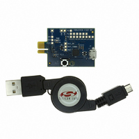
See Figure 5 below for an example hardware setup using the C8051F330 ToolStick Daughter Card.
Figure 5. Hardware Setup Example
6
Rev. 0.1
Related parts for TOOLSTICK327DC
Image
Part Number
Description
Manufacturer
Datasheet
Request
R

Part Number:
Description:
KIT TOOL EVAL SYS IN A USB STICK
Manufacturer:
Silicon Laboratories Inc
Datasheet:

Part Number:
Description:
TOOLSTICK DEBUG ADAPTER
Manufacturer:
Silicon Laboratories Inc
Datasheet:

Part Number:
Description:
TOOLSTICK BASE ADAPTER
Manufacturer:
Silicon Laboratories Inc
Datasheet:

Part Number:
Description:
TOOLSTICK DAUGHTER CARD
Manufacturer:
Silicon Laboratories Inc
Datasheet:

Part Number:
Description:
TOOLSTICK DAUGHTER CARD
Manufacturer:
Silicon Laboratories Inc
Datasheet:

Part Number:
Description:
TOOLSTICK DAUGHTER CARD
Manufacturer:
Silicon Laboratories Inc
Datasheet:

Part Number:
Description:
TOOLSTICK DAUGHTER CARD
Manufacturer:
Silicon Laboratories Inc
Datasheet:

Part Number:
Description:
KIT STARTER TOOLSTICK
Manufacturer:
Silicon Laboratories Inc
Datasheet:

Part Number:
Description:
KIT UNIVERSITY TOOLSTICK STARTER
Manufacturer:
Silicon Laboratories Inc
Datasheet:

Part Number:
Description:
DAUGHTER CARD TOOLSTICK F330
Manufacturer:
Silicon Laboratories Inc
Datasheet:

Part Number:
Description:
CARD DAUGHTER UNIVRSTY TOOLSTICK
Manufacturer:
Silicon Laboratories Inc
Datasheet:

Part Number:
Description:
DAUGHTER CARD TOOLSTICK F582
Manufacturer:
Silicon Laboratories Inc
Datasheet:

Part Number:
Description:
DAUGHTER CARD TOOLSTICK F500
Manufacturer:
Silicon Laboratories Inc
Datasheet:

Part Number:
Description:
DAUGHTER CARD TOOLSTICK F540
Manufacturer:
Silicon Laboratories Inc
Datasheet:

Part Number:
Description:
DAUGHTER CARD TOOLSTICK F560
Manufacturer:
Silicon Laboratories Inc
Datasheet: